Catalyst for purifying exhaust gas

a technology of catalyst and exhaust gas, which is applied in the direction of physical/chemical process catalyst, other chemical processes, separation processes, etc., can solve the problems of low osc, low contacting efficiency of exhaust gas in the lower layer compared with that in the upper layer, and deformation of co conversion upon fluctuation to lean atmosphere, etc., to achieve good stoichiometry-lean atmosphere conversion and improve purification performance.

Inactive Publication Date: 2010-07-20
TOYOTA JIDOSHA KK +1
View PDF50 Cites 31 Cited by
  • Summary
  • Abstract
  • Description
  • Claims
  • Application Information

AI Technical Summary

Benefits of technology

[0023]In accordance with the catalyst for purifying exhaust gas according to the present invention, the upper layer is good in term of gas diffusibility because it exhibits a thickness of 40 μm or less, and thereby the OSC, which results from the oxygen storage capacity material that is included in the lower layer, can be demonstrated maximally. Therefore, the CO conversion in stoichiometry-lean atmosphere improves especially. Moreover, since the upper layer has a thickness of 5 μm or more, the granular growth of catalytic noble metal in service can be inhibited. Therefore, it is good in terms of the durability of purifying performance.
[0024]Moreover, when a total thickness of the catalytic coating layer is adapted into being so that a range of 10 μm-80 μm accounts for 90% or more of the entirety, it is possible to avoid the rise of pressure loss while securing an absolute magnitude for oxygen sorbing / desorbing amount.

Problems solved by technology

However, in a catalyst that possesses a two-layered catalytic coating layer, the contacting efficiency to exhaust gas becomes low in the lower layer compared with that in the upper layer.
And, in the case where a catalytic coating layer that includes a co-catalyst exhibiting OSC is turned into the lower layer, it has become apparent that the OSC degrades greatly when the upper layer becomes thicker; and thereby the CO conversion upon being fluctuated to lean atmosphere degrades greatly.
But, when doing, the thickness of the catalytic coating layer as a whole becomes thicker to result in the rise of pressure loss, thereby affecting engine performance adversely.

Method used


Image

  • Catalyst for purifying exhaust gas
  • Catalyst for purifying exhaust gas
  • Catalyst for purifying exhaust gas

Examples


examples

[0045]Hereinafter, the present invention will be explained in detail by means of an example and a comparative example as well as a testing example.

example no.1

Example No. 1

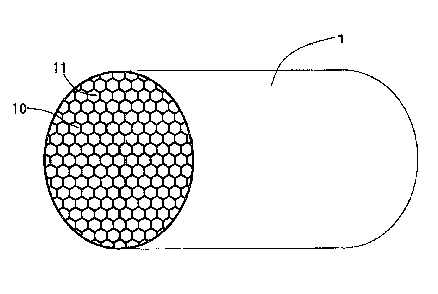
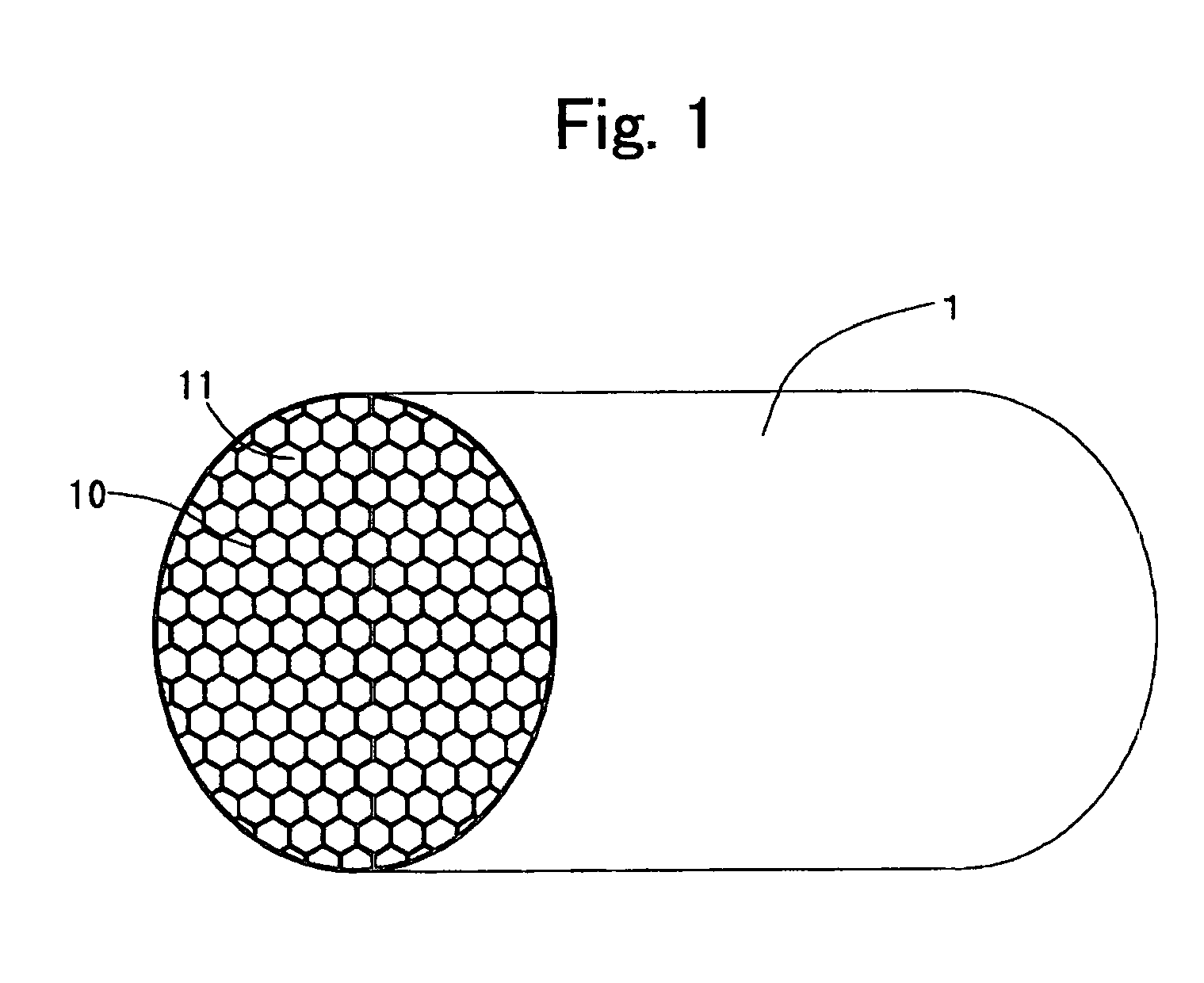
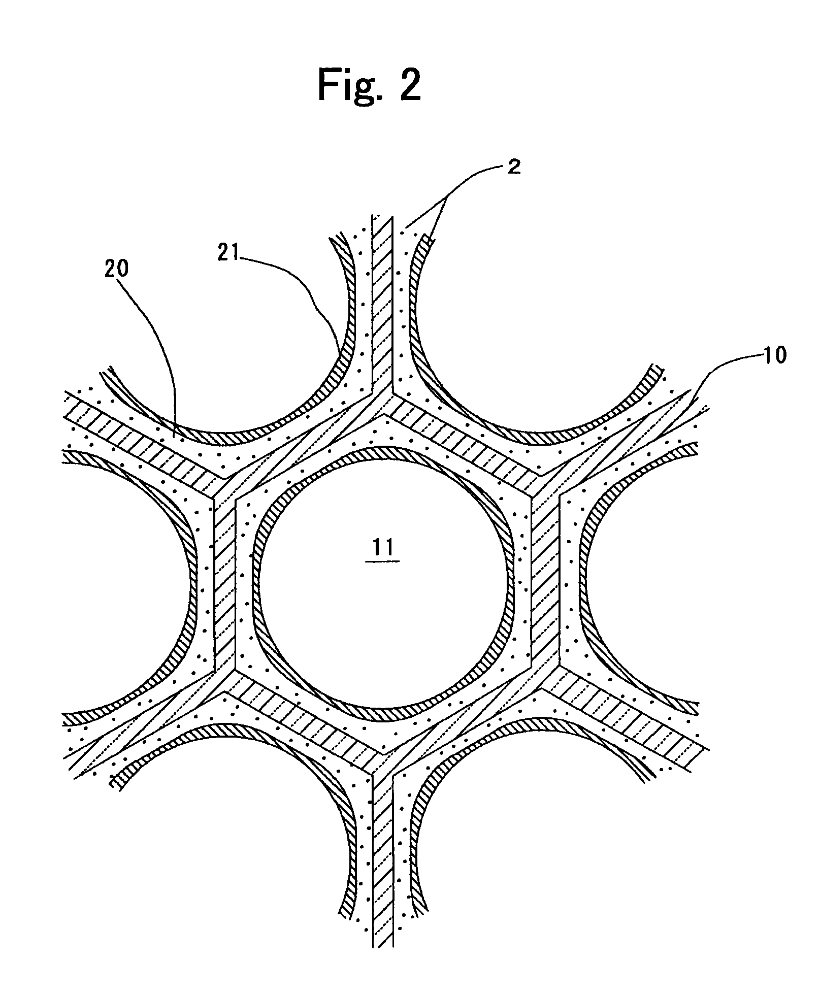
[0046]In FIG. 1 and FIG. 2, schematic diagrams of a catalyst for purifying exhaust gas according to a present example are illustrated. This catalyst comprises: a honeycomb substrate 1 that possesses hexagonally-configured cellular passages 11, which are demarcated by cellular partition walls 10, alone; and a catalytic coating layer 2 that is formed on the surface of the cellular partition walls 10. The catalytic coating layer is constituted of a lower layer 20, which is formed on the surface of the cellular partition walls 10, and an upper layer 21, which is formed on the surface of the lower layer 20. Hereinafter, the manufacturing method of this catalyst will be explained, instead of the detailed explanation on the constructions.

[0047]A predetermined amount of a CeO2—ZrO2 composite oxide powder was admixed into a predetermined amount of water, and then a predetermined amount of a Pt nitrate chemical liquid was added thereto while stirring it. This was evaporated to dr...


PUM

PropertyMeasurementUnit
thicknessaaaaaaaaaa
thicknessaaaaaaaaaa
thicknessaaaaaaaaaa

Abstract

To improve a CO conversion in stoichiometry-lean atmosphere, and additionally to prevent the rise of pressure loss.A catalytic coating layer 2 is constituted of a lower layer 20 including an oxygen storage capacity material and an upper layer 21 being formed on a surface of the lower layer 20 and including a catalytic noble metal, and a thickness of the upper layer is adapted so as to be 5 μm-40 μm. The upper layer 21 is good in terms of gas diffusibility, and thereby OSC resulting from the oxygen storage capacity material being included in the lower layer 20 is demonstrated maximally.

Description

CROSS-REFERENCE TO RELATED APPLICATIONS[0001]This application is a national phase application of International Application No. PCT / JP2007 / 064496, filed Jul. 24, 2007, and claims the priority of Japanese Application No. 2006-202099, filed Jul. 25, 2006, the contents of both of which are incorporated herein by reference.TECHNICAL FIELD[0002]The present invention relates to a catalyst for purifying exhaust gas for automotive application.BACKGROUND ART[0003]In order to purify automotive exhaust gases, various catalysts for purifying exhaust gas, such as oxidizing catalysts and three-way catalysts, have been used. These catalysts for purifying exhaust gas are those that are completed by loading a noble metal, such as Pt, Rh or Pd, onto a support comprising a porous oxide, such as γ-alumina. The porous-oxide species, or the noble-metal species have been used by combining them variously depending on their purposes.[0004]For example, although Rh is a necessary and indispensable noble metal ...

Claims


Application Information

Patent Timeline
Patent Type & Authority Patents(United States)
IPC IPC(8): B01J23/00B01J21/00B01J20/00
CPCB01D53/944B01D2255/908B01J23/63B01J37/0244B01J37/0248F01N3/0864F01N3/103F01N3/2842F01N2260/06F01N2330/06F01N2510/0682F01N2510/0684Y10T428/24149B01D53/94B01J23/38F01N3/10
Inventor YAMATO, MASANORISHINYOSHI, TAKATOSHISUZAWA, TAKUMIITO, KEIJI
Owner TOYOTA JIDOSHA KK
Why Eureka
Try Eureka