Optical sensor for monitoring electrical current or power

a technology of optical sensors and current or power, applied in the direction of photometry, electric vehicles,spectrum investigation, etc., can solve the problems of inability to provide correct measurements, inability to use types of sensors in presence of strong electromagnetic fields or high voltage environments, and inability to adapt to the type of sensors

Active Publication Date: 2010-07-20
OPSENS SOLUTIONS
View PDF10 Cites 28 Cited by
  • Summary
  • Abstract
  • Description
  • Claims
  • Application Information

AI Technical Summary

Problems solved by technology

Although these electrical measurement methods have been widely used, there are still today specific applications where they fail to provide correct measurements.
For example, these types of sensors often cannot be used in presence of strong electromagnetic fields or in high voltage environments.
More particularly, these types of sensors are generally not well adapted for the assessment of electro-explosive devices (EED).
EEDs are susceptible to initiation by electromagnetic fields as a result of current induced in the EED circuit.
This method has disadvantages: the response of the thermocouple sensor may be altered by the presence of EM fields and alternatively, the electrical leads of this sensor may alter the EM field under which the EED is being tested.
This method suffers from poor sensitivity, authors claiming a sensitivity of 20 dB below the no fire threshold (NFT) point while acceptable sensitivity required for ordnance components is in the range of 35 dB.
One of the drawbacks of this technique is its slow response time.
This method comes with drawbacks as it is based on an interferometric principle.
Among others, the method suffers form great sensitivity to mechanical vibration and optical fiber movement due to induced modal noise in the multimode optical fiber.
The disadvantage of this method is that the electrical property of the sensing element may be affected by the presence of strong EM fields.
These fields may also induced current in the electrical conductors that connect to the sensing element therefore giving false measurements.

Method used


Image

  • Optical sensor for monitoring electrical current or power
  • Optical sensor for monitoring electrical current or power
  • Optical sensor for monitoring electrical current or power

Examples


Embodiment Construction

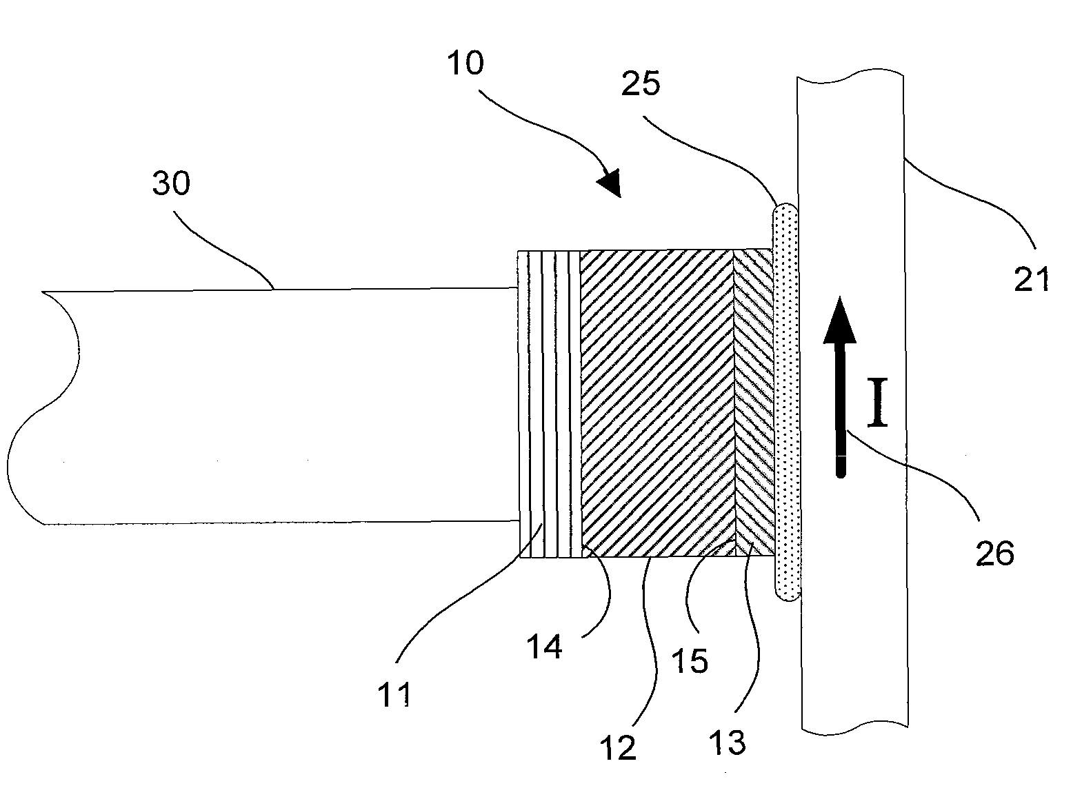
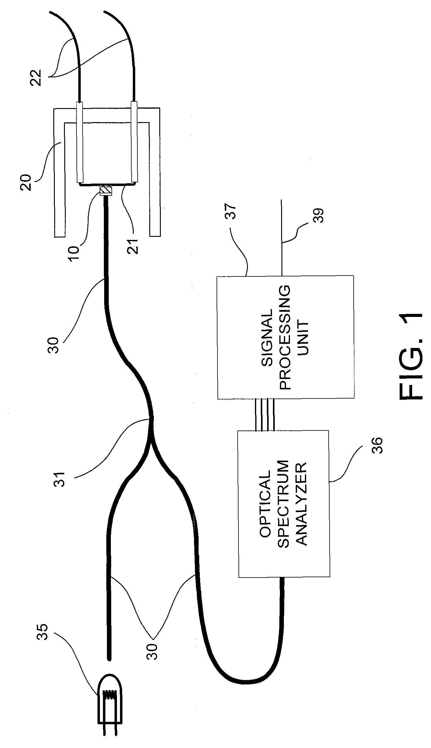
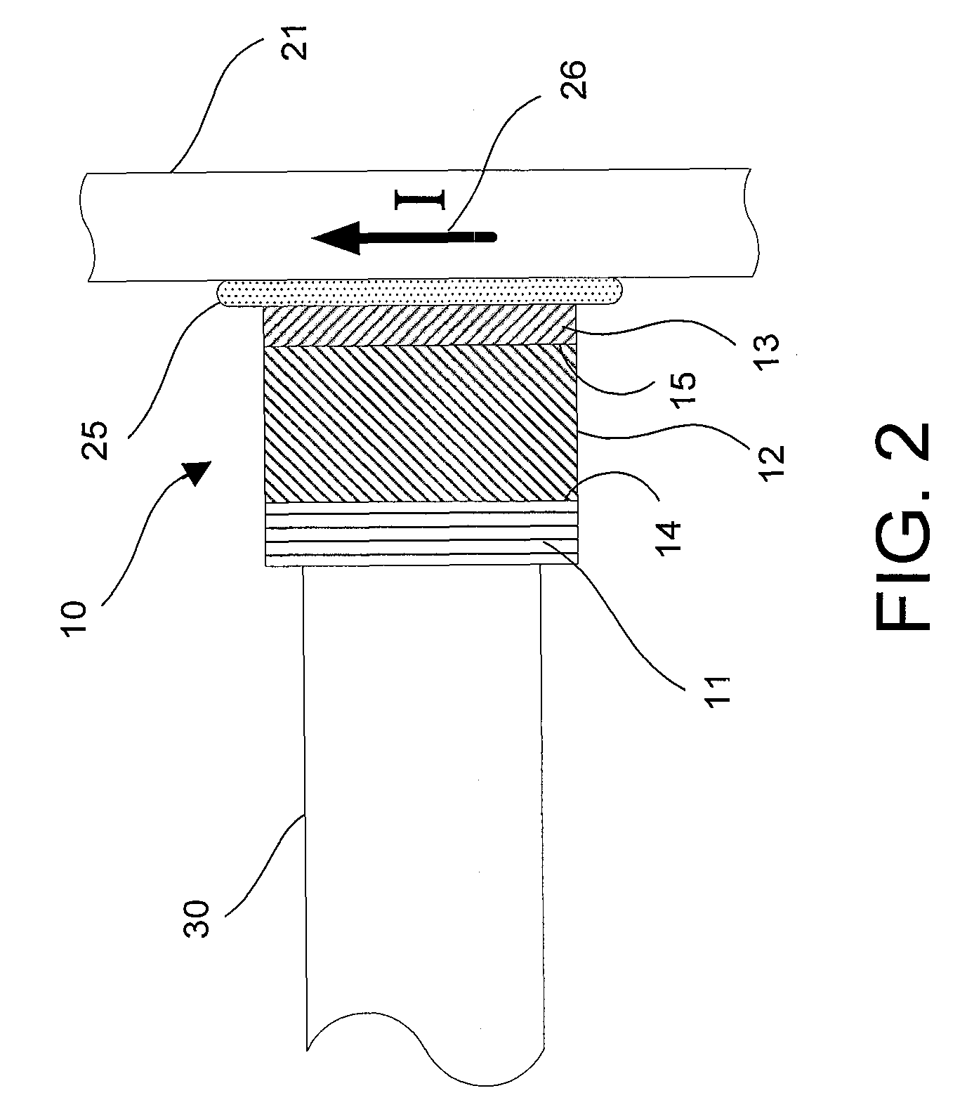
[0024]Referring to FIGS. 1, 2 and 3, a simple optical sensor for monitoring electrical current and power uses a temperature sensitive element 12 (forming part of the optical sensor 10 of FIG. 1) which has a characteristic in its optical absorption spectrum which varies with temperature. More specifically, the temperature sensitive element 12 is made of a semiconductor material having a transition, e.g. an edge, the spectral position of the optical absorption edge varying with temperature. The optical sensor 10 is put in thermal contact with the element 21 of the device 20 to be monitored. In an example, the monitored element 21 shown in FIG. 1 is a bridge-wire of an electro-explosive device 20. Current flowing through (or power dissipated by) the bridge-wire 21 of the monitored electro-explosive device 20 is monitored by measuring the spectral shift 41 of the semiconductor absorption edge 40 (see FIG. 3) caused by the temperature increase of the bridge-wire 21 of the monitored elect...


PUM


Abstract

The present invention provides an optical sensor for monitoring current or power in a monitored element of a device such as a bridge-wire or hot-wire of electro-explosive devices. The optical sensor comprises an optical sensor made of semiconductor material. The semiconductor material comprises an absorption edge which is sensitive to a temperature variation. The semiconductor material is for placing in thermal contact with the monitored element of the device, whereby, when the current or power varies in the monitored element, it causes a variation in temperature in the semiconductor element and hence a spectral shift of the absorption edge which can be measured and which is representative of current and power variation.

Description

CROSS-REFERENCE TO RELATED APPLICATIONS[0001]This application claims priority under 35 USC §119(e) of U.S. provisional patent application 60 / 781,383 filed Mar. 13, 2006, the specification of which is hereby incorporated by reference.TECHNICAL FIELD[0002]The present invention relates to electrical current or electrical power sensors and, more specifically, to sensors used for monitoring electrical current or electrical power on electro-explosive devices.BACKGROUND OF THE ART[0003]Various electrical current and electrical power sensors, based on direct or indirect electrical measurement methods, are readily available on the market. An old method still in use today consists of measuring the voltage drop across a resistor placed in the current path. There also exist more sophisticated techniques based on the Hall effects or magnetoresistive effects. Although these electrical measurement methods have been widely used, there are still today specific applications where they fail to provide...

Claims


Application Information

Patent Timeline
Patent Type & Authority Patents(United States)
IPC IPC(8): G01J1/04G01J5/08G01J1/42
CPCG01K11/3213G01R15/146G01R15/247
Inventor DUPLAIN, GAETANBELLEVILLE, CLAUDE
Owner OPSENS SOLUTIONS
Why Eureka
Try Eureka