RFID token with multiple interface controller

a technology of interface controllers and tokens, applied in the field of smart card technology, can solve the problems of not being well accepted by users, requiring relatively high power, and relatively expensive readers

Inactive Publication Date: 2010-07-27
DPD PATENT TRUST
View PDF89 Cites 273 Cited by
  • Summary
  • Abstract
  • Description
  • Claims
  • Application Information

AI Technical Summary

Benefits of technology

[0182]An embodiment of the invention is generally directed to a compact personal RFID token and a compact RFID reader token with a slot or hatch to accommodate a transponder. The compact personal RFID token is a transponder device with multiple interfaces (mechanical, contactless, wireless and optical) and extended memory (flash or hard disk drive), which can be used in a plethora of applications such logical and physical access, secure identification, ticketing, payment and e-commerce. The compact personal RFID reader token is an RFID reader with similar interfaces as described above but with a slot allowing the user to insert a transponder device or contactless fob. The fob can also be a dual interface device with smart card contacts and contactless function. The primary difference between the compact personal RFID token and the RFID reader token is that the user can insert any contactless fob (e.g. payment fob) into the portable reader. This means that the user has flexibility in deciding which contactless fob should be used in a particular application and user can use the reader to check the status of his or her balance. In short, the reader and transponder is one single apparatus.

Problems solved by technology

(However, these readers are relatively costly, and have not been well accepted by users.)
It is good at real-time data in synchronous connected oriented mode, but requires relatively high power, so is unsuitable for extremely small battery-powered applications.Byte A binary digital signal is essentially a string of ones and zeros—in other words, one voltage level or another, typically with no values in-between.
Since having only two fingers (or one, depending on how you count) is not a very useful means of representing a wide number of variables, such as letters of the alphabet, it soon became apparent to bundle bits into bytes, such as eight bits to a byte.
Packet filtering is fairly effective and transparent to users, but it is difficult to configure.
In addition, it is susceptible to IP spoofing.Application gateway: Applies security mechanisms to specific applications, such as FTP and Telnet servers.
This is very effective, but can impose a performance degradation.Circuit-level gateway: Applies security mechanisms when a TCP or UDP connection is established.
An intranet's Web sites look and act just like any other Web sites, but the firewall surrounding an intranet fends off unauthorized access.
Because an SSID can be sniffed in plain text from a packet it does not supply any security to the network.
Unfortunately, it is also much more expensive to produce than DRAM.
WLANs, which are over radio waves, do not have the same physical structure and therefore are more vulnerable to tampering.
However, it has been found that WEP is not as secure as once believed.
Wi-Fi is poor at real-time data, until 802.11e is deployed.

Method used


Image

  • RFID token with multiple interface controller
  • RFID token with multiple interface controller
  • RFID token with multiple interface controller

Examples


embodiment 100

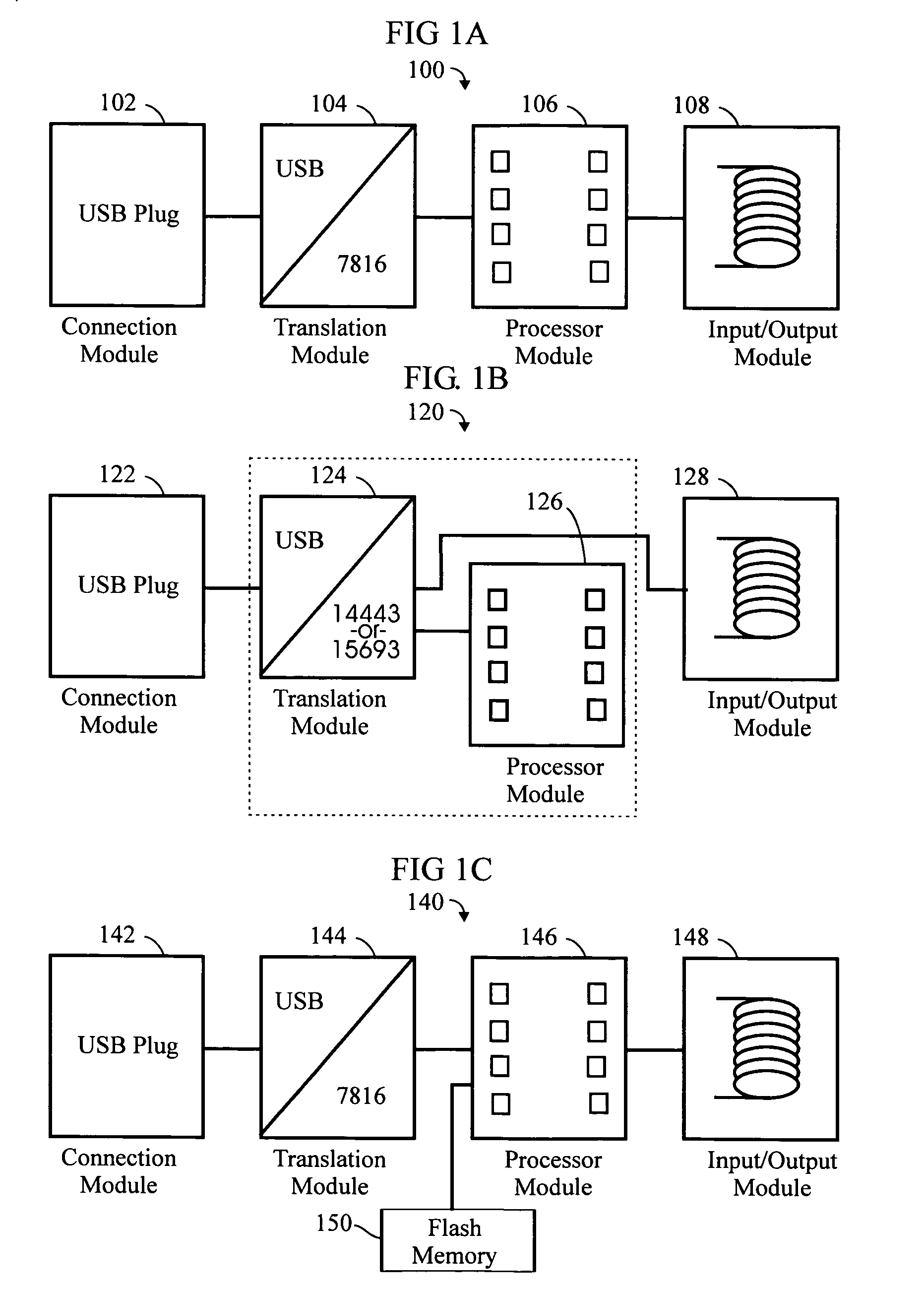
[0224]FIG. 1C is a schematic block diagram of another exemplary embodiment 140 of the invention, based on the embodiment 100 of FIG. 1A. The major components are:[0225]a connection module 142;[0226]a translation module 144;[0227]a processor module 146; and[0228]an input / output (I / O) module 148.

embodiment 140

[0229]In this embodiment 140, a flash memory device 150 can be included, with a storage capacity of 1 to 4 megabytes (or more) for the purpose of running applications. The memory management for the device may be handled by a crypto controller operating system with an 8 bit address bus in the dual interface (DI) chip. The flash memory device may be any suitable device including, but not limited to, Secure Digital (SD) card format, and including SIM card. (A crypto controller is a processor chip capable of encrypting and decrypting data to be stored in internal or external memory.)

[0230]The apparatus may incorporate firewall functionality to protect an Internet-capable appliance.

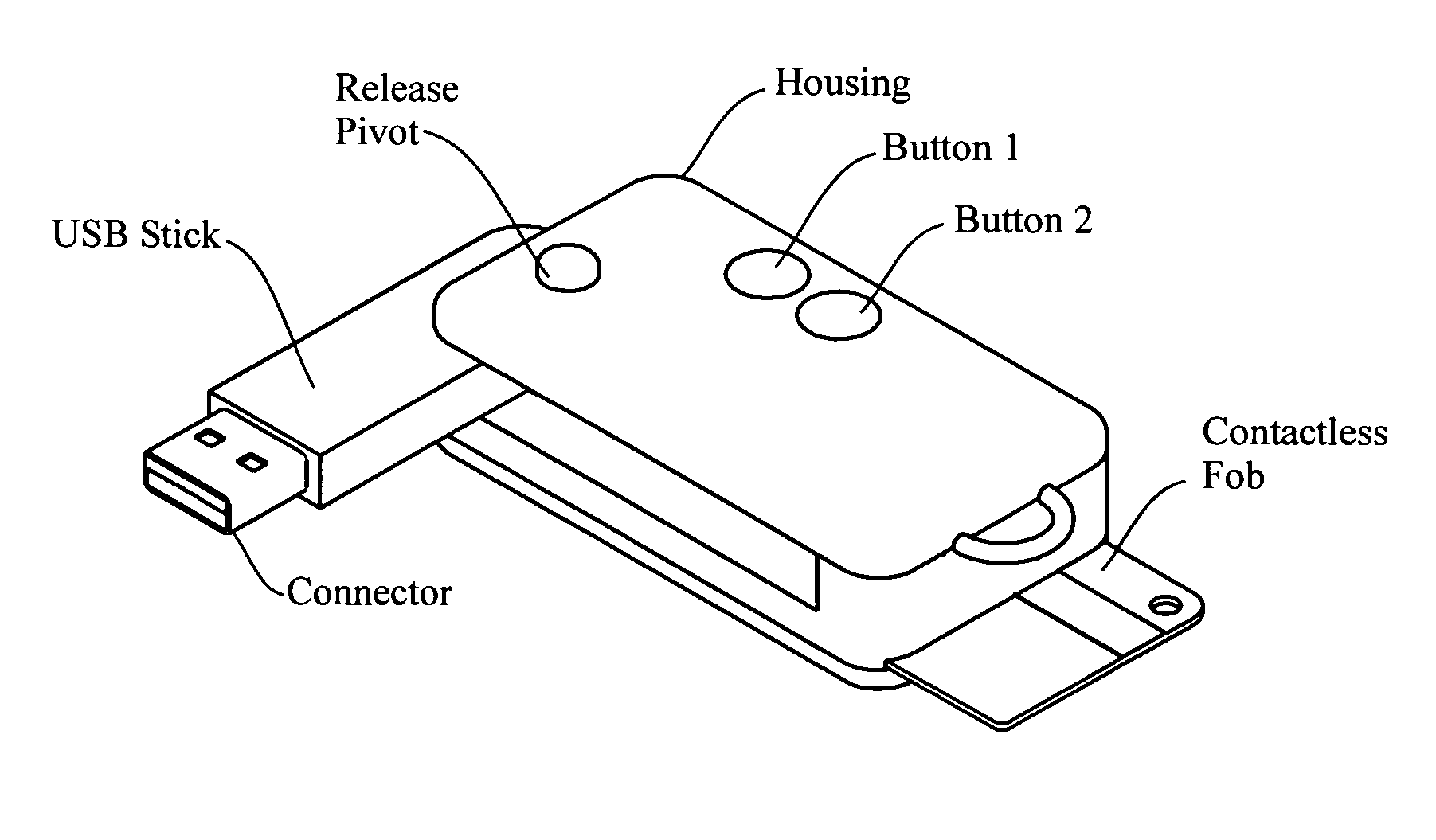
[0231]The invention may be embodied in the form of a “smart fob” apparatus, having the general physical configuration (size, shape, form) of a conventional USB memory fob. (Refer to FIG. 2A of the '296 application.) This is basically a device (200) having the elongate size and general shape of your finger, com...

exemplary embodiment 400

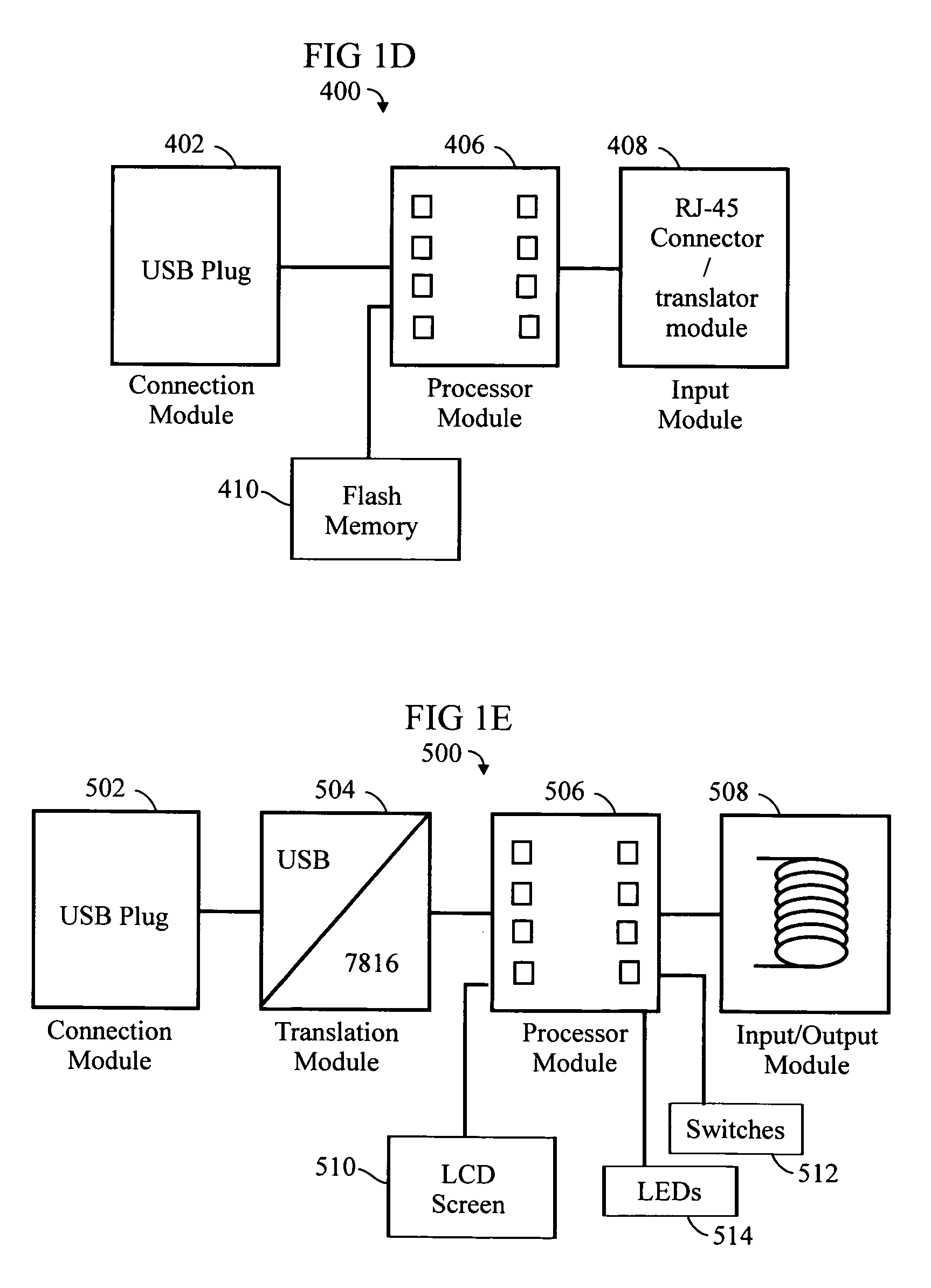
[0238]FIG. 1D (FIG. 4 of the '296 application) is a schematic block diagram of an exemplary embodiment 400 of the invention wherein the device can be used as a firewall to protect, for example, a PC. The functionality is described elsewhere in greater detail. The principal components of the device 400 are:[0239]a connection module 402 for plugging into the USB (or, network, LAN / Ethernet, or Fast Ethernet 10 / 100 MBit) port of a PC;[0240]a processor module 406; and[0241]an input module 408 which, unlike other embodiments, need not perform contactless (or wireless) functions, but rather is socket (or plug), such as RJ-45, for connecting to a telephone line (or the like) supporting a DSL (or the like) connection to the Internet.[0242]The device 400 may also incorporate flash memory 510 (compare 150).

[0243]FIG. 1E (FIG. 5 of the '296 application) is a schematic block diagram of an exemplary embodiment 500 of the invention, based on the embodiment 100 of FIG. 1. The major components are:[...


PUM


Abstract

An RFID token apparatus has a connection module for interfacing with an appliance capable of communicating and interacting with remote servers and networks, a translation module for moving signals between a USB interface and a smart card interface, a processor module which may be capable of operating as a dual-interface (DI) chip; and an input / output module having at least one RF antenna and a modulator. An RFID-contactless interface according to ISO 14443 & ISO 15693 and / or NFC. A wireless interface according to ZIGBEE wireless, BLUETOOTH wireless, WLAN 802.11, UWB, USB wireless and / or any similar interface. An RFID reader apparatus has a housing; a slot for a contact or contactless fob; and a USB stick alternately protruding from the housing and retracted within the housing.

Description

CROSS-REFERENCE TO RELATED APPLICATIONS[0001]This is a continuation-in-part of U.S. Ser. No. 10 / 990,296 filed Nov. 16, 2004 now U.S. Pat. No. 7,213,766.[0002]This is a continuation-in-part of U.S. Ser. No. 11 / 295,685 filed Dec. 6, 2005 now U.S. Pat. No. 7,632,113.[0003]This is a non-provisional filing of U.S. Ser. No. 60 / 652,895 filed Feb. 15, 2005.[0004]This is a non-provisional filing of U.S. Ser. No. 60 / 660,398 filed Mar. 10, 2005.[0005]This is a non-provisional filing of U.S. Ser. No. 60 / 664,974 filed Mar. 24, 2005.[0006]Priority is claimed from the following:[0007]Provisional Application No. 60 / 734,409 filed Nov. 8, 2005[0008]Provisional Application No. 60 / 725,818 filed Oct. 12, 2005[0009]Provisional Application No. 60 / 708,707 filed Aug. 16, 2005[0010]Provisional Application No. 60 / 708,628 filed Aug. 16, 2005[0011]Provisional Application No. 60 / 691,337 filed Jun. 16, 2005[0012]Provisional Application No. 60 / 685,503 filed May 27, 2005[0013]Provisional Application No. 60 / 664,974 ...

Claims


Application Information

Patent Timeline
Patent Type & Authority Patents(United States)
IPC IPC(8): G06K19/06G08B13/14G06K5/00G06K7/00G06K19/00H04H1/00H04H20/93H04H60/37H04H60/63H04H60/74
CPCG06K7/0004G06K19/07732G06K19/07733G06K19/07769H04H60/372H04H60/63H04H60/74H04H20/93H04L67/02G06Q20/353G07F7/0873G06Q20/321
Inventor FINN, DAVIDRYAN, DENNIS
Owner DPD PATENT TRUST
Why Eureka
Try Eureka