Method and apparatus for optical gain fiber having segments of differing core sizes

a technology of optical gain fiber and segment, applied in the direction of lasers, electromagnetic transmission, transmission, etc., can solve the problems of large bending losses of fibers with very low values of na, limited power that can be generated from fiber lasers and fiber-laser amplifiers, and disadvantages of such fibers, so as to increase the amount of pump power available, reduce the amount of pump power, and enhance energy extraction

Active Publication Date: 2010-08-03
LOCKHEED MARTIN CORP
View PDF10 Cites 70 Cited by
  • Summary
  • Abstract
  • Description
  • Claims
  • Application Information

AI Technical Summary

Benefits of technology

[0009]In some embodiments, the invention provides methods and apparatus for enhanced energy extraction from an optical fiber amplifier by removing ASE light from the amplifier at locations along the fiber to reduce the amount of pump power used to amplify the ASE and thus increase the amount of pump power available to amplify the signal light. In some embodiments, subsequent sections of fiber have larger diameters, and/or have cores that have larger diame...

Problems solved by technology

The power that can be generated from fiber lasers and fiber-laser amplifiers can often be limited by nonlinear optical effects in the gain and/or delivery fibers used in the system.
Using relatively large-core, low-NA fibers with mode-filtering techniques has been demonstrated to achieve good beam quality, but there are practical disadvantages to the use of such fibers.
Fibers with very low values of NA exhibit large bending losses, even for relatively large-radius bends.
With fibers having the lowest NA, the fiber must be kept quite straight, otherwise the optical amplifier and/or laser has very low efficiency as the bending loss becomes too high.
Since a typical l...

Method used


Image

  • Method and apparatus for optical gain fiber having segments of differing core sizes
  • Method and apparatus for optical gain fiber having segments of differing core sizes
  • Method and apparatus for optical gain fiber having segments of differing core sizes

Examples


Embodiment Construction

[0036]Although the following detailed description contains many specifics for the purpose of illustration, a person of ordinary skill in the art will appreciate that many variations and alterations to the following details are within the scope of the invention. Accordingly, the following preferred embodiments of the invention are set forth without any loss of generality to, and without imposing limitations upon the claimed invention.

[0037]In the following detailed description of the preferred embodiments, reference is made to the accompanying drawings that form a part hereof, and in which are shown by way of illustration specific embodiments in which the invention may be practiced. It is understood that other embodiments may be utilized and structural changes may be made without departing from the scope of the present invention.

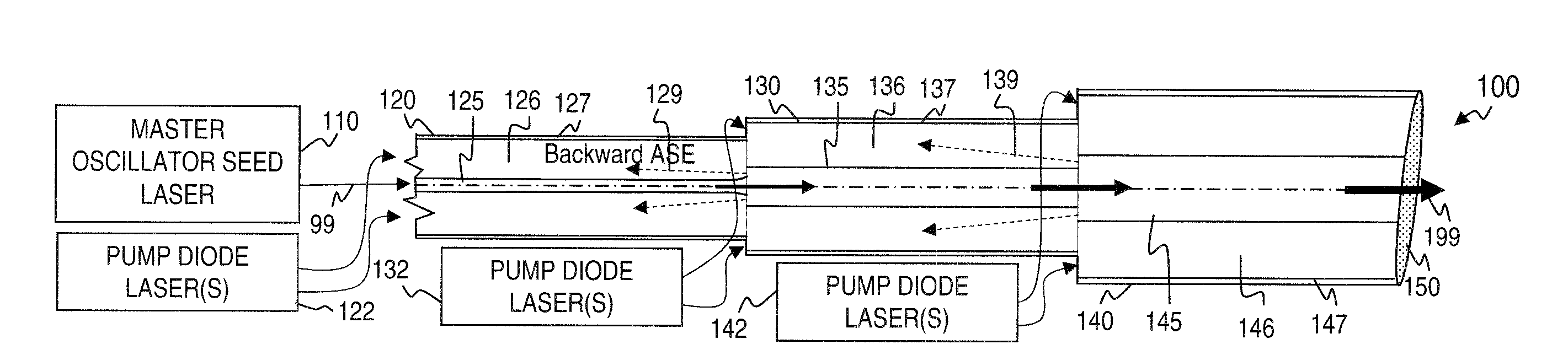
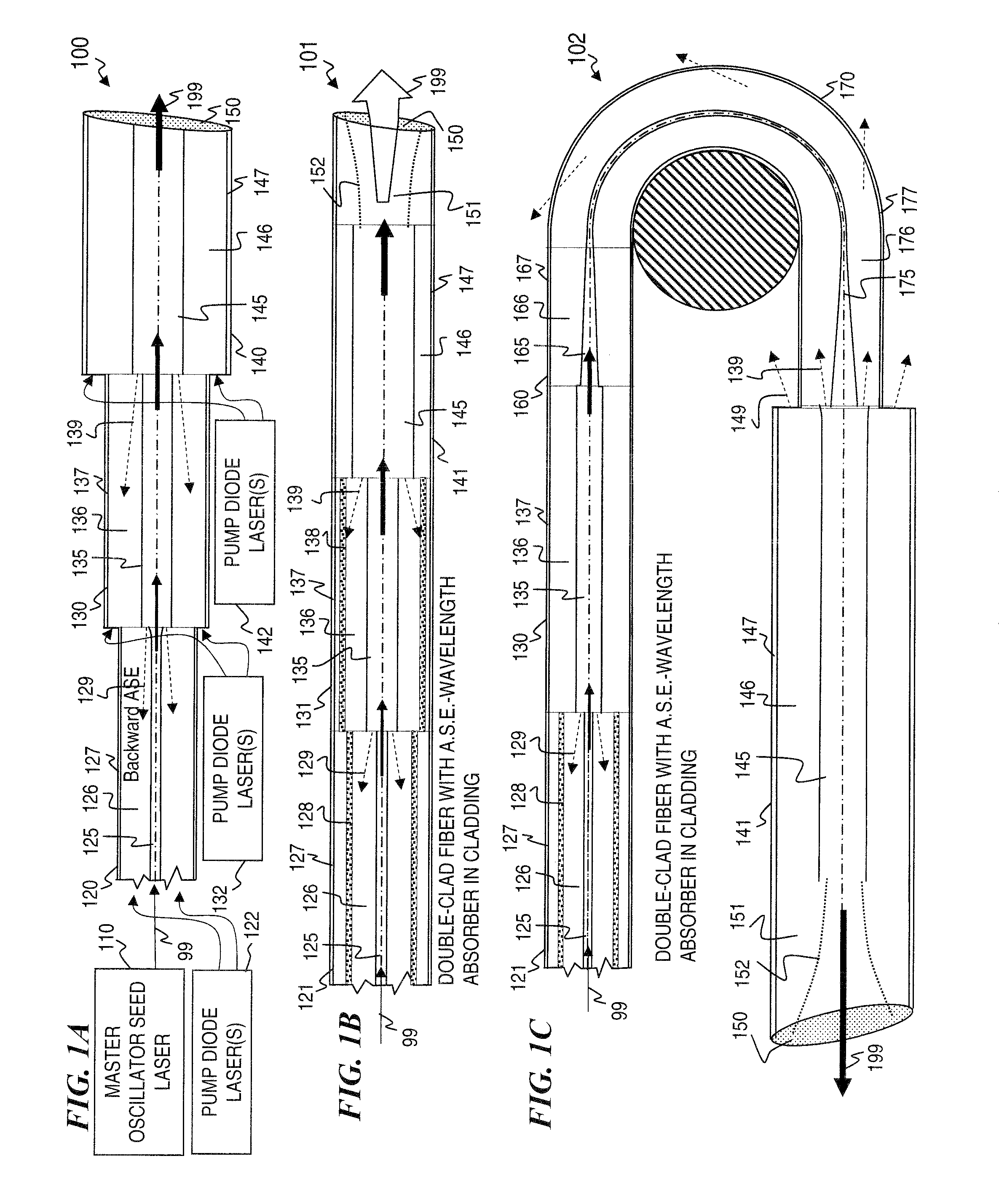
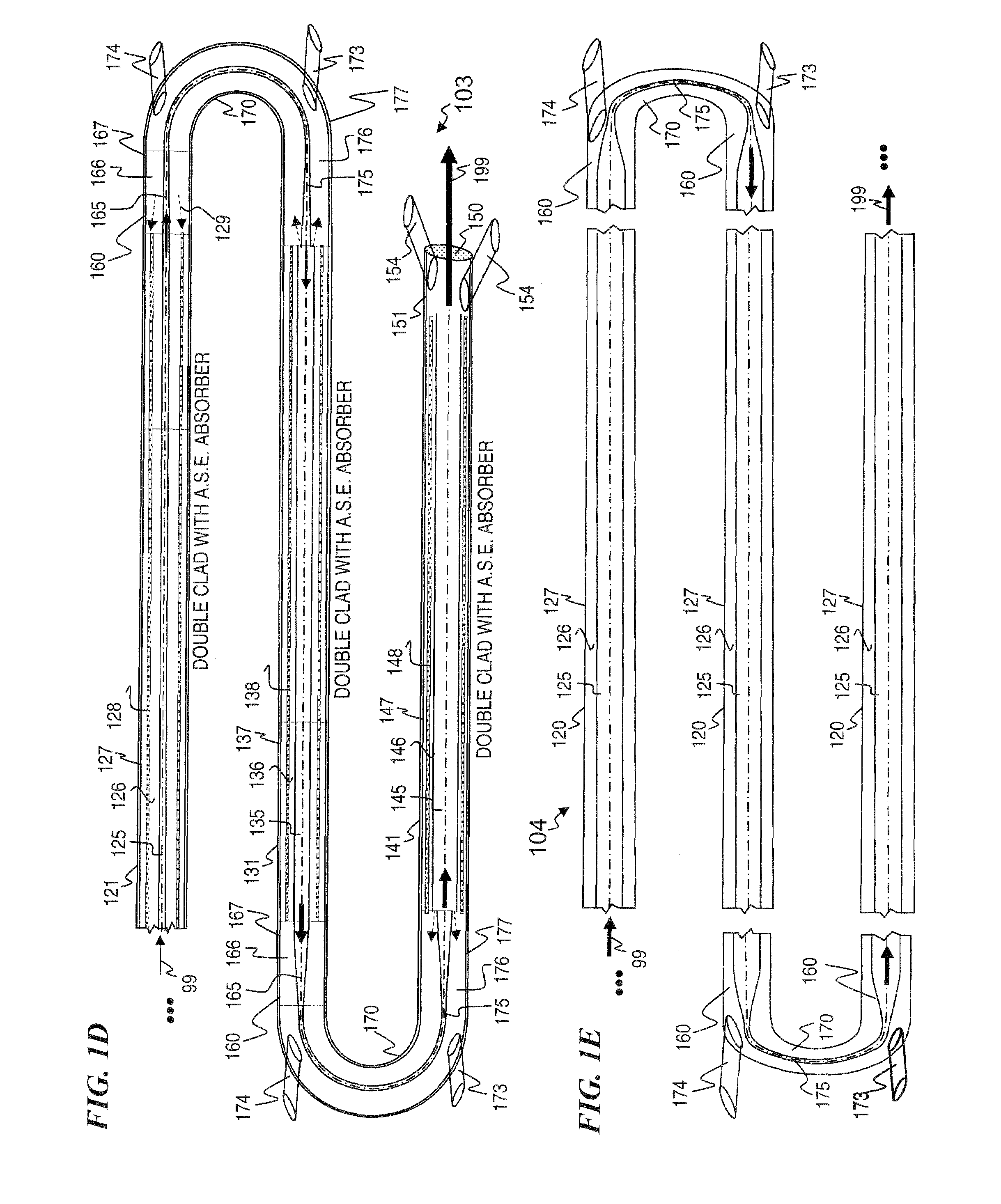
[0038]The leading digit(s) of reference numbers appearing in the Figures generally corresponds to the Figure number in which that component is first introduc...


PUM

PropertyMeasurementUnit
Diameteraaaaaaaaaa
Sizeaaaaaaaaaa
Frequencyaaaaaaaaaa

Abstract

Apparatus and method for amplifying laser signals using segments of fibers of differing core diameters and/or differing cladding diameters to suppress amplified spontaneous emission and non-linear effects such as four-wave mixing (FWM), self-phase modulation, and stimulated Brillouin and/or Raman scattering (SBS/SRS). In some embodiments, different core sizes have different sideband spacings (spacing between the desired signal and wavelength-shifted lobes). Changing core sizes and providing phase mismatches prevent buildup of non-linear effects. Some embodiments further include a bandpass filter to remove signal other than the desired signal wavelength and/or a time gate to remove signal at times other than during the desired signal pulse. Some embodiments include photonic-crystal structures to define the core for the signal and/or the inner cladding for the pump. Some embodiments include an inner glass cladding to confine the signal in the core and an outer glass cladding to confine pump light in the inner cladding.

Description

STATEMENT REGARDING FEDERALLY SPONSORED RESEARCH OR DEVELOPMENT[0001]This invention was made with Government support under contract F29601-98-D-0190 awarded by the U.S. Navy. The Government has certain rights in the invention.CROSS-REFERENCE TO RELATED APPLICATIONS[0002]This invention is related toU.S. patent application Ser. No. 11 / 488,910 filed Jul. 17, 2006 (now U.S. Pat. No. 7,539,231) titled “APPARATUS AND METHOD FOR GENERATING CONTROLLED-LINEWIDTH LASER-SEED-SIGNALS FOR HIGH-POWERED FIBER-LASER AMPLIFIER SYSTEMS”,U.S. patent application Ser. No. 11 / 426,302 filed Jun. 23, 2006 (now U.S. Pat. No. 7,526,167) titled “APPARATUS AND METHOD FOR A HIGH-GAIN DOUBLE-CLAD AMPLIFIER”,U.S. patent application Ser. No. 11 / 420,730 filed May 26, 2006 (now U.S. Pat. No. 7,430,352) titled “MULTI-SEGMENT PHOTONIC-CRYSTAL-ROD WAVEGUIDES FOR AMPLIFICATION OF HIGH-POWER PULSED OPTICAL RADIATION AND ASSOCIATED METHOD”,U.S. patent application Ser. No. 11 / 420,732 filed May 27, 2006 (now U.S. Pat. No. 7...

Claims


Application Information

Patent Timeline
IPC IPC(8): H01S3/00B29C48/10B29C48/71
CPCB29C47/0026B29C47/707H01S3/06754H01S3/06716H01S3/06729H01S3/06741H01S3/06745H01S2301/02H01S3/06758H01S3/094007H01S3/094019H01S3/09415H01S3/0675B29C48/10B29C48/71H01S3/06733H01S3/094053
Inventor SAVAGE-LEUCHS, MATTHIAS P.
Owner LOCKHEED MARTIN CORP
Why Eureka
Try Eureka