
Linear digital phase interpolator and semi-digital delay locked loop (DLL)

a digital phase interpolator and semi-digital delay technology, applied in the field of semi-digital delay locked loop (dll), can solve the problems of difficult tracking and difficult use of conventional digital phase interpolators, and achieve the effect of efficient control

Active Publication Date: 2010-08-10
SAMSUNG ELECTRONICS CO LTD
View PDF7 Cites 27 Cited by
  • Summary
  • Abstract
  • Description
  • Claims
  • Application Information

AI Technical Summary

Benefits of technology

The invention provides a digital phase interpolator that can perform linear phase interpolation regardless of the order in which input signals are received. The invention also includes a semi-digital delay locked loop (DLL) that efficiently controls the digital phase interpolator. The technical effect of the invention is to improve the accuracy and reliability of phase interpolation in high-speed data transmission systems.

Problems solved by technology

This operational result is fine for some applications, but presents a problem for other applications and circuit.
For example, when the relative (lead / lag) phases for two input signals received by a digital phase interpolator, such as one incorporated within a semi-digital DLL, continuously change, it is difficult to track which one of the two input signals is first received, and the conventional digital phase interpolator becomes difficult to use.

Method used


Image

  • Linear digital phase interpolator and semi-digital delay locked loop (DLL)
  • Linear digital phase interpolator and semi-digital delay locked loop (DLL)
  • Linear digital phase interpolator and semi-digital delay locked loop (DLL)

Examples


Embodiment Construction

[0014]Hereinafter, embodiments of the present invention will be described with reference to the accompanying drawings. It should be noted, however, the invention may be variously embodied and is not limited to only the illustrated embodiments. Throughout the drawings and written description, like reference numerals and indicators are used to denote like or similar elements.

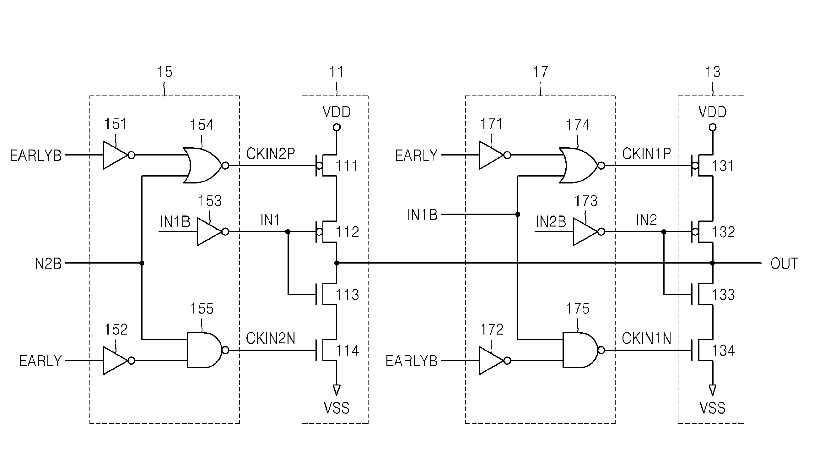
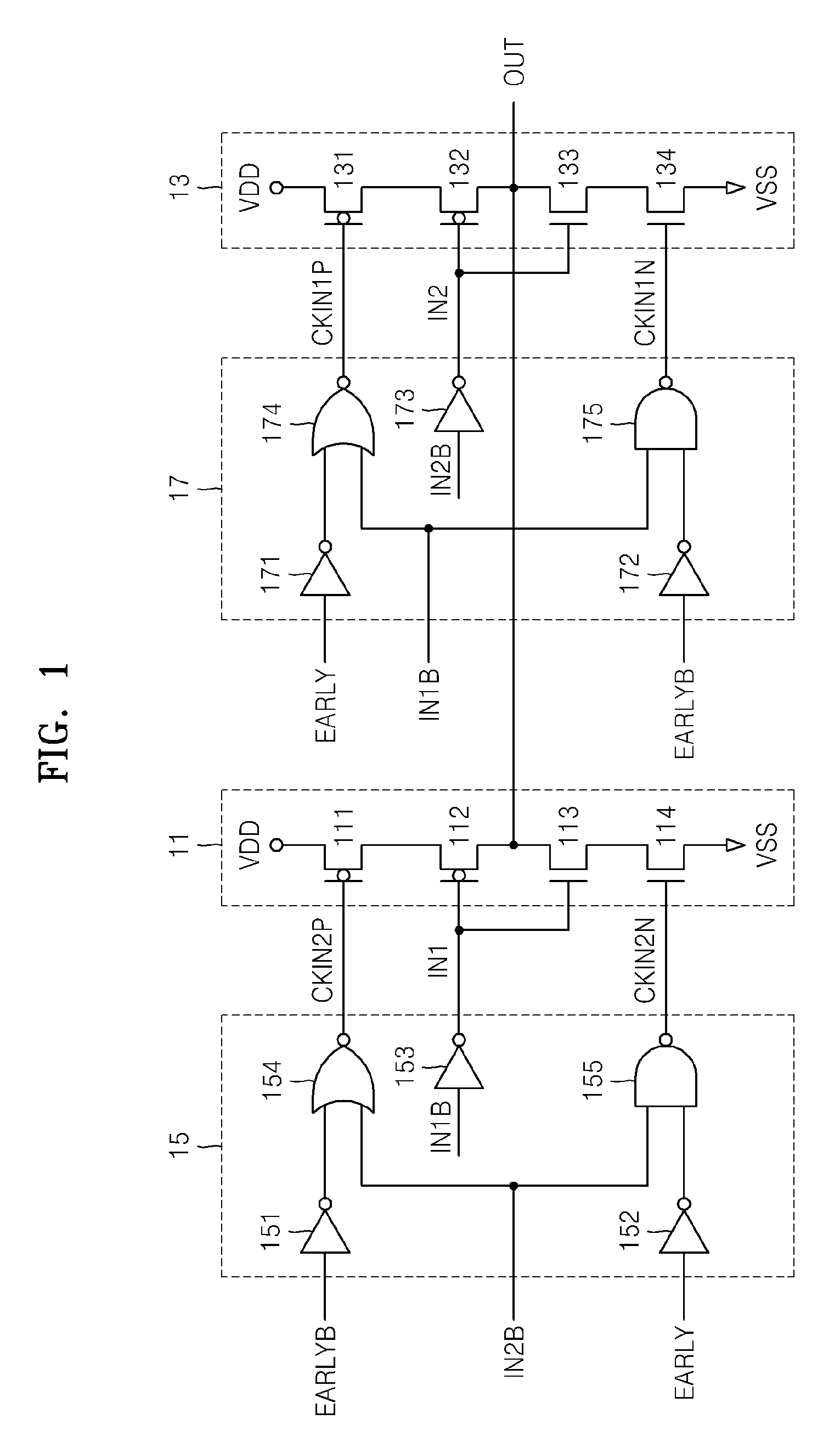
[0015]FIG. 1 is a circuit diagram illustrating a digital phase interpolator according to an embodiment of the present invention.

[0016]Referring to FIG. 1, the digital phase interpolator includes a first clocked inverter 11, a second clocked inverter 13, a first control circuit 15, and a second control circuit 17.

[0017]The first clocked inverter 11 and the second clocked inverter 13 are connected to a common output terminal OUT. The first clocked inverter 11 is controlled by a phase indicating signal EARLY and an inverted signal EARLYB thereof (actually controlled by clock signals CKIN2P and CKIN2N generated by the...


PUM


Abstract

Provided are a digital phase interpolator, which performs linear phase interpolation irrelevantly to input order of two input signals, and a semi-digital delay locked loop (DLL), which includes and controls the same. The phase interpolator includes: a first clocked inverter controlled by a phase indicating signal and providing a first output signal to a common output terminal by inverting a first input signal, and a second clocked inverter controlled by the phase indicating signal and providing a second output signal to the common output terminal by inverting the second input signal. The second clocked inverter is clocked by the first input signal when the phase indicating signal is in a first logic state, and the first clocked inverter is clocked by the second input signal when the phase indicating signal is in a second logic state. The phase indicating signal indicates a lead / lag phase relationship between the first and second input signals and is generated in a controller of a circuit of the semi-digital DLL.

Description

CROSS-REFERENCE TO RELATED PATENT APPLICATION[0001]This application claims the benefit of Korean Patent Application No. 10-2007-0106210 filed on Oct. 22, 2007, the subject matter of which is hereby incorporated by reference.BACKGROUND[0002]The present invention relates generally to semiconductor devices, and more particularly, to a digital phase interpolator and a semi-digital delay locked loop (DLL) incorporating same.[0003]Numerous semiconductor devices use specialized circuits to adjust timing delays for input / output (I / O) signals, clock signals, etc. The digital phase interpolator is one such circuit and is commonly used to adjust the timing of internal clock signal(s) within semiconductor devices.[0004]The digital phase interpolator receives two input signals having different phases and generates an output signal having a defined phase between the two received input signals. The digital phase interpolator may be implemented in a simple circuit, and can precisely output a define...

Claims


Application Information

Patent Timeline
Patent Type & Authority Patents(United States)
IPC IPC(8): H03H3/00H03K5/13
CPCH03L7/0814H03L7/07H03L7/081
Inventor KIM, JIN-GOOKBAE, SEUNG-JUNPARK, KWANG-IL
Owner SAMSUNG ELECTRONICS CO LTD
Learn More