Antireflection film

a technology of anti-reflection film and anti-reflection film, applied in the field of anti-reflection film, can solve problems such as impaired chromaticity balance, and achieve the effects of excellent chromaticity balance property, sufficient reduction of reflectivity, and suppression of flares and ghosts

Inactive Publication Date: 2010-08-10
FUJI PHOTO OPTICAL CO LTD
View PDF6 Cites 6 Cited by
  • Summary
  • Abstract
  • Description
  • Claims
  • Application Information

AI Technical Summary

Benefits of technology

[0050]The antireflection film according to any of the above configurations is disposed on the substrate, and includes at least first to eighth layers stacked sequentially from the opposite side to the substrate. The first and fourth layers exhibit the refractive index of 1.35 to 1.50 with respect to the d-line. The third and fifth layers exhibit the refractive index of 1.55 to 1.85 with respect to the d-line. The second and sixth layers exhibit the refractive index that is in a range from 1.70 to 2.50 with respect to the d-line, and that is higher than the refractive indices of the third and fifth layers. Although the number of stacked layers is relatively small, therefore, the reflectivity can be sufficiently reduced in a broader wavelength band. When such an antireflection film is applied to an optical system in an imaging apparatus such as a photographic camera or a broadcast camera, accordingly, generations of flare and ghost can be suppressed, and a more excellent chromaticity balance property can be obtained.

Problems solved by technology

When the total number of the optical components is large, the total amount of reflected light is correspondingly increased, and hence problems such as flare or ghost are caused in, for example, a broadcast camera.
Therefore, the chromaticity balance is impaired, and the white balance must be adjusted in the whole imaging apparatus.

Method used


Image

  • Antireflection film
  • Antireflection film
  • Antireflection film

Examples


first embodiment

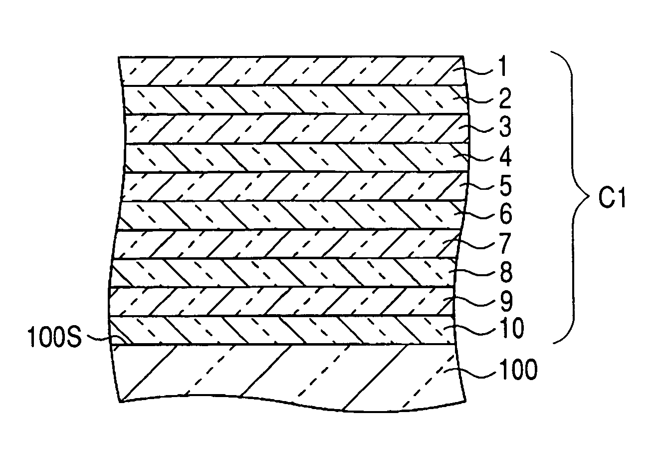
[0092]FIG. 1 is a schematic section view showing the configuration of an antireflection film C1 according to a first embodiment of the invention. The antireflection film C1 of FIG. 1 corresponds to a first numerical example (FIGS. 9 and 10) which will be described later.

[0093]The antireflection film C1 is a multilayer film which is disposed on the surface 100S of an optical substrate 100, and which consists of ten layers in total, that is, first to tenth layers 1 to 10 that are stacked sequentially from the opposite side to the optical substrate 100. In the embodiment, the surface 100S is a flat face. The invention is not limited to this, and the surface may be a curved face. Namely, a lens having a spherical surface or an aspherical surface may be used as the optical substrate 100, and the antireflection film C1 may be disposed on the spherical or aspherical surface.

[0094]The optical substrate 100 is made of a transparent material such as glass or a crystal material. Specifically, ...

second embodiment

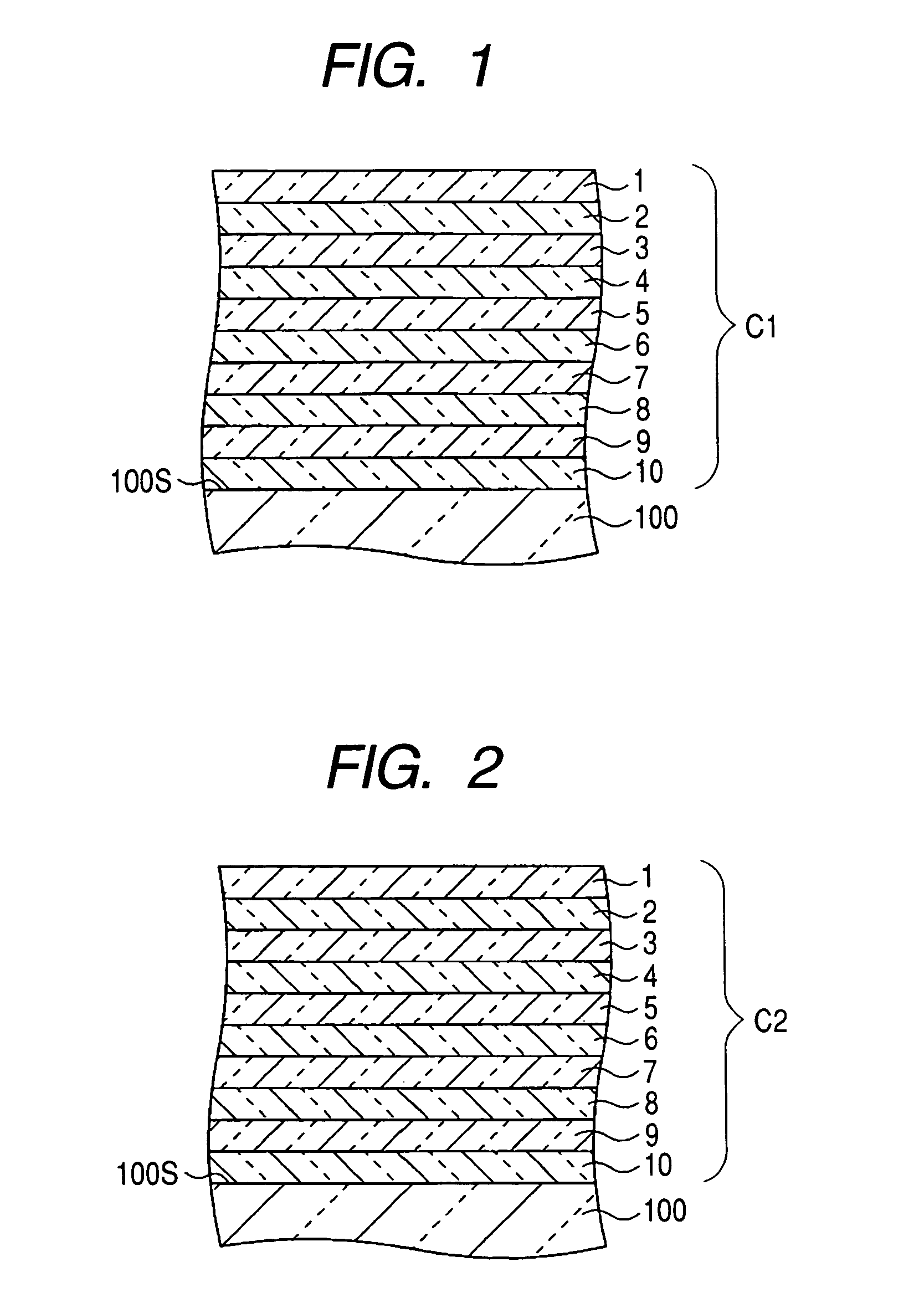
[0101]FIG. 2 is a schematic section view showing the configuration of an antireflection film C2 according to a second embodiment of the invention. The antireflection film C2 of FIG. 2 corresponds to a second numerical example (FIGS. 11 to 18) which will be described later.

[0102]In the same manner as the antireflection film C1 of the first embodiment described above, the antireflection film C2 is a multilayer film which is disposed on the surface 100S of the optical substrate 100, and which consists of ten layers in total, that is, first to tenth layers 1 to 10 that are stacked sequentially from the opposite side to the optical substrate 100. In the following description of the antireflection film C2, components which are substantially different from those of the antireflection film C1 of the first embodiment will be mainly described, and descriptions of the same components will be accordingly omitted.

[0103]Preferably, the optical substrate 100 is made of a transparent material which...

third embodiment

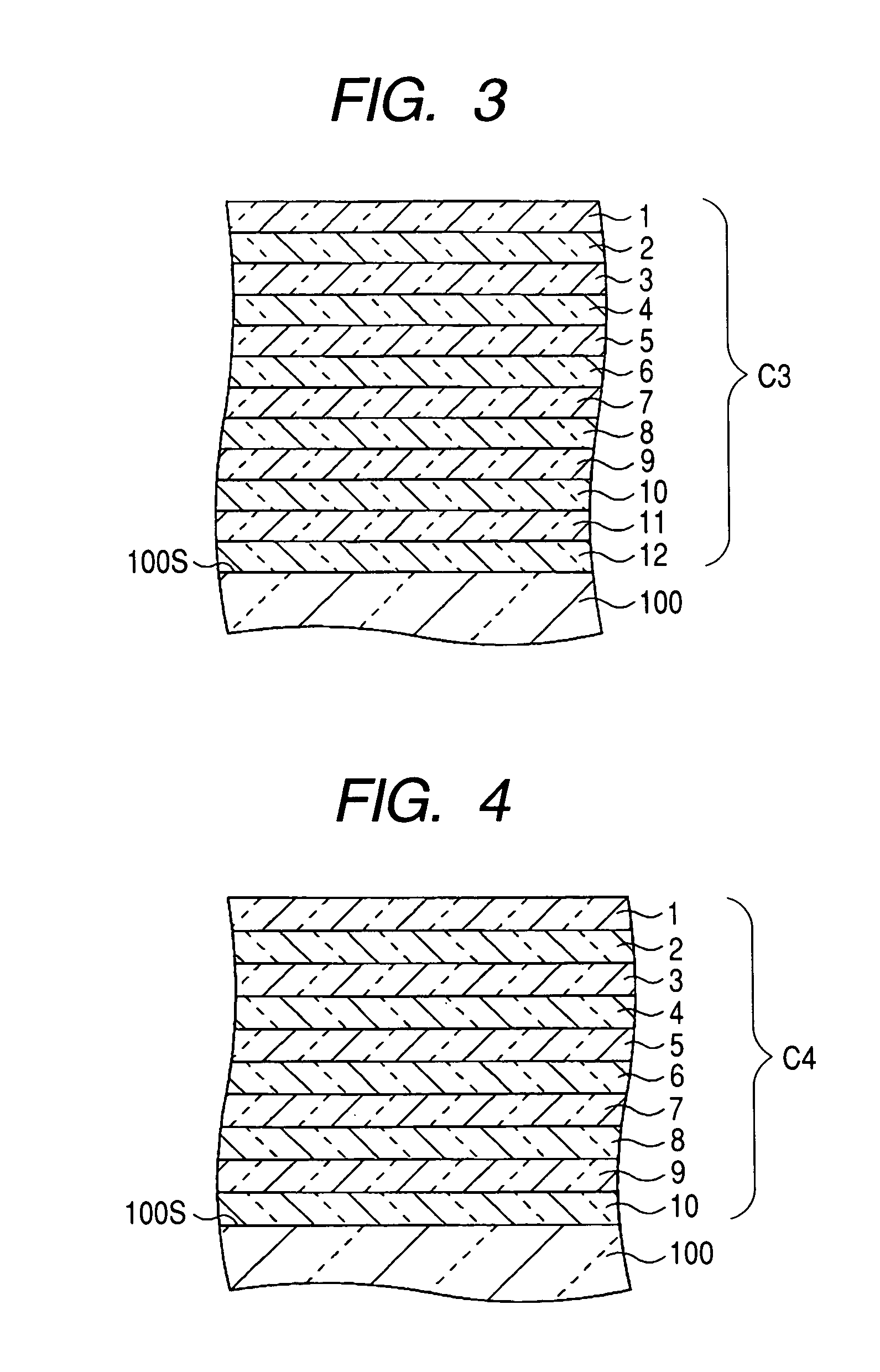
[0108]FIG. 3 is a schematic section view showing the configuration of an antireflection film C3 according to a third embodiment of the invention. The antireflection film C3 of FIG. 3 corresponds to a third numerical example (FIGS. 19 and 20) which will be described later.

[0109]The antireflection film C3 is a multilayer film which is disposed on the surface 100S of the optical substrate 100, and which consists of twelve layers in total, that is, first to twelfth layer 1 to 12 that are stacked sequentially from the opposite side to the optical substrate 100. In the following description of the antireflection film C3, components which are substantially different from those of the antireflection films C1, C2 of the first and second embodiments will be mainly described, and descriptions of the same components will be accordingly omitted.

[0110]Preferably, the optical substrate 100 is made of a transparent material which exhibits a refractive index of 1.61 to 1.67 with respect to the d-lin...


PUM

PropertyMeasurementUnit
refractive indexaaaaaaaaaa

Abstract

An antireflection film is disposed on a surface of an optical substrate, and consists of first to tenth layers to stacked sequentially from the opposite side to the optical substrate. The first layer, the fourth layer and the ninth layer are low-refractive index layers made of a low-refractive index material exhibiting a refractive index of 1.35 to 1.50 with respect to the d-line. The third layer, the fifth layer, the seventh layer and the tenth layer are intermediate-refractive index layers made of an intermediate-refractive index material exhibiting a refractive index of 1.55 to 1.85 with respect to the d-line.The second layer, the sixth layer and the eighth layer are high-refractive index layers made of a high-refractive index material exhibiting a refractive index that is in a range from 1.70 to 2.50 with respect to the d-line, and that is higher than the refractive index of the intermediate-refractive index material.

Description

BACKGROUND OF THE INVENTION[0001]1. Technical Field[0002]The present invention relates to an antireflection film which is formed on one face of an optical component such as a lens or a filter to produce an antireflective effect on light of a predetermined wavelength band.[0003]2. Description of the Related Art[0004]In an imaging apparatus such as a photographic camera or a broadcast camera, usually, many optical components such as lenses, prisms, and filters are arranged along the optical path. When light is incident on the surface of such an optical component, part of the light is formed as reflected light. When the total number of the optical components is large, the total amount of reflected light is correspondingly increased, and hence problems such as flare or ghost are caused in, for example, a broadcast camera. The reflectivities at the surfaces of the optical components are distributed with respect to the wavelength of the incident light, and show various wavelength dependen...

Claims


Application Information

Patent Timeline
Patent Type & Authority Patents(United States)
IPC IPC(8): G02B1/10B32B7/02B32B9/00G02B1/11G02B1/115
CPCG02B1/115G02B27/0012
Inventor TERAYAMA, ETSUO
Owner FUJI PHOTO OPTICAL CO LTD
Why Eureka
Try Eureka