Optical pickup, optical disc drive device, and optical information device

Active Publication Date: 2010-08-10
PANASONIC CORP
View PDF23 Cites 6 Cited by
  • Summary
  • Abstract
  • Description
  • Claims
  • Application Information

AI Technical Summary

Benefits of technology

[0012]It is an object of the present invention to provide an optical pickup more compact and of wider spherical aberration correction range than the optical pickup proposed in the prior art, an optical disc drive device using the optical pickup, and an optical information device.
[0029]According to the present invention, the guide member is arranged extending to the side of the reflecting surface of the rising mirror, and the slidable part moving along the guide member is configured projecting out towards the rising mirror side further than the lens holder, and thus the spherical aberration correction lens can be moved very close to the rising mirror and a large movement range can be obtained. Therefore, a large correction range of the spherical aberration can be obtained. Since the spherical aberration correction lens is configured to project towards the rising mirror side with respect to the lens holder, the projecting portion of the spherical aberration correction lens can be arranged, in an overlapping state, on the reflecting surface of the rising mirror arranged in a tilted manner. Therefore, it can be suitably used in the information recording medium including two or more information recording layers requiring a large spherical aberration correction range.
[0030]Since the movement range of the spherical aberration lens can be made wider, the optical pickup can be configured small with respect to the absolute necessary movement range. Thus, further miniaturization from the conventional technique is achieved. The blur of the lens holder with respect to the guide member is prevented as the slidable part is formed projecting out with respect to the lens holder.
[0031]Since the spherical aberration correction lens and the slidable part are both projected out towards the rising mirror side with respect to the lens holder, the barycenter thereof approach each other, and thus moment by inertial force is less likely to be applied when driving the lens holder. Furthermore, since the spherical aberration correction lens is projected with respect to the lens holder when attaching the spherical aberration correction lens to the lens holder, the visibility is satisfactory, and forgetting of attachment of the lens is prevented. Moreover, since the lens having one side configured with large curvature is used, the attachment direction can be easily visually checked, and the front and back attachment direction of the lens can be easily checked.

Problems solved by technology

The configuration of the optical system becomes more complicated to respond to recordation and reproduction of a plurality of types of optical information recording media, and the number of parts increases.

Method used


Image

  • Optical pickup, optical disc drive device, and optical information device
  • Optical pickup, optical disc drive device, and optical information device
  • Optical pickup, optical disc drive device, and optical information device

Examples


first embodiment

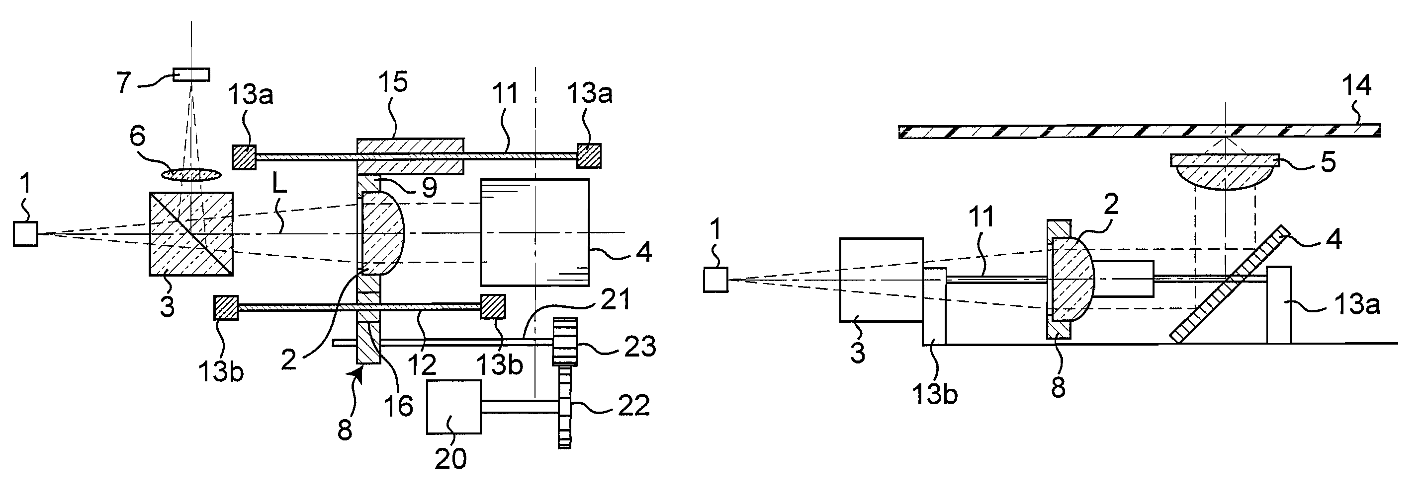
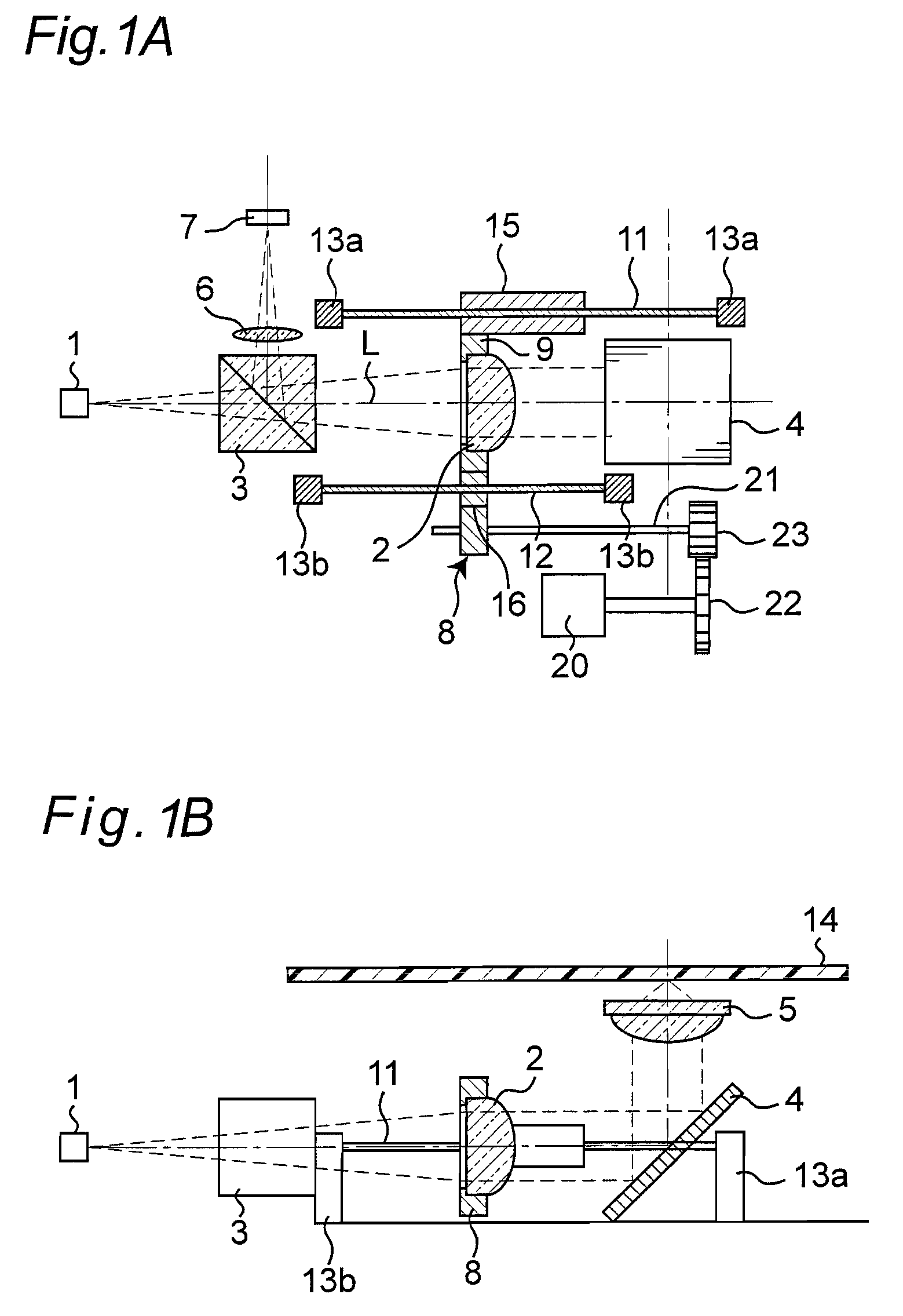
[0047]FIGS. 1A and 1B are frame format views describing a configuration of an optical pickup according to a first embodiment of the present invention, where FIG. 1A is a plan view of the optical pickup and FIG. 1B is a side view of the optical pickup.

[0048]In the figures, 14 denotes an optical disc serving as an information recording medium, 1 denotes a laser diode serving as a light source, 2 denotes a collimator lens serving as a spherical aberration correction lens, 3 denotes a beam splitter, 4 denotes a rising mirror, 5 denotes an objective lens, 6 denotes a detection lens, and 7 denotes a photodetector including a photoelectric conversion element etc. 20 denotes a stepping motor and 21 denotes a ball screw. In the plan view of FIG. 1A, the illustration of the objective lens 5 and the optical disc 14 is omitted.

[0049]When performing recordation / reproduction with respect to the optical disc 14, the light beam emitted from the laser diode 1 is passed through the beam splitter 3 an...

second embodiment

[0080]FIG. 6 is a frame format view describing a configuration of an optical pickup according to a second embodiment of the present invention.

[0081]In FIG. 6, the laser diode 1 serving as a light source, the collimator lens 2 serving as a spherical aberration correction lens, the beam splitter 3, the rising mirror 4, the objective lens 5, the photodetector 7 including the photoelectric conversion element, the stepping motor 20, and the ball screw 21 have the same configuration as the first embodiment, and thus the description will be omitted. 31 is a light quantity monitor for detecting the light quantity of the laser diode 1 by detecting the light quantity of the light reflected from the optical disc 14.

[0082]In the present embodiment, the proximate position of the objective lens of a housing 30 for accommodating each member configuring the optical pickup is formed with a cutout 33 so that a spindle motor 40 and the housing 30 do not interfere. If the optical pickup becomes closest...

third embodiment

[0097]FIG. 7A and FIG. 7B are frame format views describing a configuration of an optical pickup according to a third embodiment of the present invention, where FIG. 7A is a plan view of the optical pickup, and FIG. 7B is a side view of the optical pickup.

[0098]In FIG. 7A and FIG. 7B, the laser diode 1 serving as a light source, the beam splitter 3, the rising mirror 4, the objective lens 5, the photodetector 7 including the photoelectric conversion element, the stepping motor 20, and the ball screw 21 have the same configuration as the first embodiment, and thus the description will be omitted. 31 is a light quantity monitor for detecting the light quantity of the laser diode 1 by detecting the light quantity of the light reflected from the optical disc 14.

[0099]In the present embodiment, the collimator lens 2 for converting the laser light to a parallel light is fixed. A beam expander unit 60 for changing the beam system of the light beam from the light source is arranged between ...


PUM


Abstract

A small optical pickup of wide spherical aberration correction range includes a rising mirror for perpendicularly deflecting a light beam and guiding the light beam to an objective lens; a spherical aberration correction lens having one surface formed to a larger curvature than the other surface; a lens holder for holding the correction lens so that the surface of large curvature projects towards the rising mirror side; an axially extending guide member; and a slidable part slidable along the guide member. The projecting portion of the slidable part is configured to be fitted within the side surface of the reflecting surface of the rising mirror, and the projecting portion from the lens holder of the spherical aberration correction lens overlaps the reflecting surface of the rising mirror when the spherical aberration correction lens approaches the rising mirror the most.

Description

TECHNICAL FIELD[0001]The present invention relates to an optical pickup device using a spherical aberration correction mechanism employing a lens drive device enabling a lens configuring the optical pickup device to be movable in an optical axis direction, an optical disc drive device using the optical pickup, and an optical information device.BACKGROUND ART[0002]Recently, development in compact and large-capacity optical disc devices is advancing to handle high definition still images and moving images and the like in the field of recording or reproducing information signals using an optical disc as an information recording medium.[0003]The optical disc device is equipped with an optical pickup for forming a beam spot on an information recording surface of the optical disc. In the optical pickup, the light beam emitted from the light source is influenced by spherical aberration when passing through a transparent protective substrate layer which protects the information recording la...

Claims


Application Information

Patent Timeline
IPC IPC(8): G02B17/00G11B7/135
CPCG11B7/1353G11B7/1362G11B7/1376G11B7/13925G11B2007/0013
Inventor MATSUZAKI, KEIICHIKOMMA, YOSHIAKITANAKA, TOSHIYASUSANO, KOUSEIWAKABAYASHI, KANJIWADA, HIDENORI
Owner PANASONIC CORP
Why Eureka
Try Eureka