Method that allows flexible evaluation of power-gated circuits

Active Publication Date: 2010-08-10
ANSYS INC
View PDF4 Cites 11 Cited by
  • Summary
  • Abstract
  • Description
  • Claims
  • Application Information

AI Technical Summary

Problems solved by technology

Leakage currents flow in logic circuits from a power supply node into the ground node because the switching characteristics of the transistors in the logic circuits are not ideal (i.e., the transistors cannot be completely shut off).

Method used


Image

  • Method that allows flexible evaluation of power-gated circuits
  • Method that allows flexible evaluation of power-gated circuits
  • Method that allows flexible evaluation of power-gated circuits

Examples


Embodiment Construction

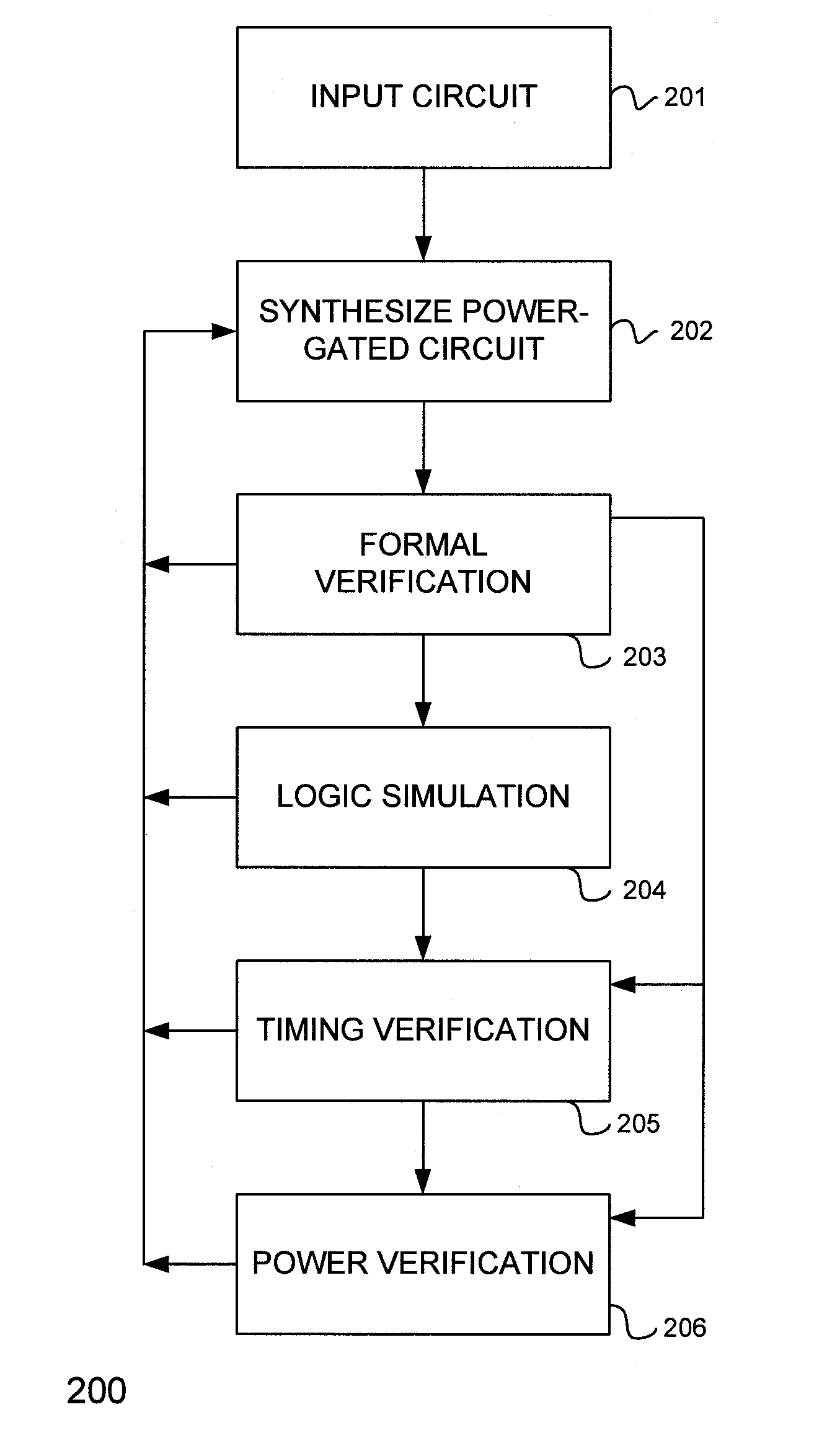
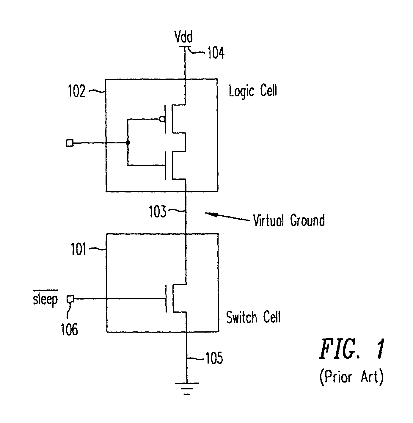
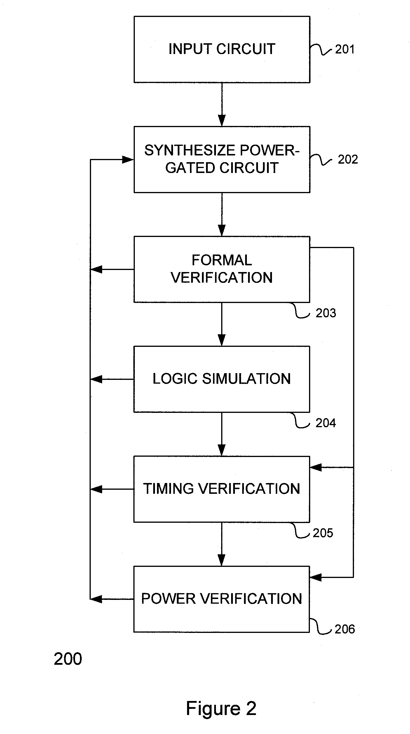
[0029]According to the present invention, a design automation method allows a “virtual ground” or “virtual power” network (a “virtual power signal network”) to be modeled both as a virtual power signal network and as a signal network. Under the present invention, the design automation system may elect to treat the virtual power signal as a power signal or power rail, in the sense of the conventional power and ground signals, at certain stages of the design process (e.g., during “formal verification,” which verifies that the synthesized power-gated circuit is functionally identical to the input non-power gated circuit), and applies power network analysis tools for evaluation and verification. At other stages of the design process, the design automation system may elect to treat the virtual power signal network as a signal network (e.g., logic simulation and timing analysis), and applies signal analysis tools for evaluation and verification. This method provides, among other benefits,...


PUM


Abstract

A method and a design automation tool are provided for use in conjunction with designing logic circuits that implement virtual power signals. The method includes providing in a model for each virtual power signal an attribute that distinguishes the virtual power signal from both a logic signal and a power signal. The method also includes one or more circuit analysis, processing and synthesis tool that takes advantage of such an attribute. That is, within the design automation tool, capabilities are provided so that a virtual power signal may be processed in some instances as a logic signal, and at some instance as indistinguishable to a power rail signal or reference.

Description

CROSS-REFERENCE TO RELATED APPLICATIONS[0001]This patent application is a continuation-in-part application of—thus claiming priority to—U.S. patent application, entitled “DESIGN METHOD AND ARCHITECTURE FOR POWER GATE SWITCH PLACEMENT”, Ser. No. 10 / 998,204, filed on Nov. 26, 2004, now U.S. Pat. No. 7,590,962. The disclosure of the Application is hereby incorporated by reference in its entirety.BACKGROUND OF THE INVENTION[0002]1. Field of the Invention[0003]The present invention relates to a method for designing multi-threshold complementary metal-oxide-semiconductor (MTCMOS) circuits and the physical architecture of the circuits resulting from using such a method. In particular, the present invention relates to a design method to allow flexible simulation and verification of an MTCMOS circuit.[0004]2. Discussion of the Related Art[0005]A significant concern in integrated circuit design is reducing leakage currents. Leakage currents flow in logic circuits from a power supply node into...

Claims


Application Information

Patent Timeline
Patent Type & Authority Patents(United States)
IPC IPC(8): G06F17/50
CPCG06F17/5031G06F17/5068G06F17/5077H01L27/0207H01L27/11807H03K19/0016G06F30/3312G06F30/394G06F30/00G06F30/39G06F2119/06G06F2119/12
Inventor FRENKIL, GERALD L.
Owner ANSYS INC
Why Eureka
Try Eureka