
Low resistance tunneling magnetoresistive sensor with natural oxidized double MgO barrier

a magnetoresistive sensor, low resistance technology, applied in the field of high-performance tunneling magnetoresistive (tmr) sensors, can solve the problems of difficult control of ra mean, too high read head applications, etc., and achieve the effect of improving the uniformity of barrier thickness and oxidation

Active Publication Date: 2010-08-24
HEADWAY TECH INC
View PDF16 Cites 27 Cited by
  • Summary
  • Abstract
  • Description
  • Claims
  • Application Information

AI Technical Summary

Benefits of technology

[0012]One objective of the present invention is to provide a TMR sensor with a natural oxidized MgO barrier layer to improve the uniformity of the barrier thickness and oxidation compared with rf-sputtered or reactive sputtered MgO barriers.
[0013]A second objective of the present invention is to provide a TMR sensor having a substantially higher MR ratio than realized with sensors comprised of an AlOx barrier layer while achieving a low RA value and low magnetostriction required for advanced read head applications.
[0014]A further objective of the present invention is to provide a method of forming a TMR sensor that satisfies the first and second objectives and is cost effective.

Problems solved by technology

However, RA values in the MTJs mentioned above are in the range of 240 to 10000 ohm-um2 which is too high for read head applications.
Although a high MR ratio and low RA have been demonstrated in MTJs having a MgO barrier layer, there are still many issues to be resolved before such configurations can be implemented in a TMR sensor of a read head.
For example, the annealing temperature needs to be lower than 300° C. for read head processing, and rf-sputtered MgO barriers make control of RA mean and uniformity more difficult than with conventional DC-sputtered and subsequently naturally oxidized AlOx barriers.

Method used


Image

  • Low resistance tunneling magnetoresistive sensor with natural oxidized double MgO barrier
  • Low resistance tunneling magnetoresistive sensor with natural oxidized double MgO barrier
  • Low resistance tunneling magnetoresistive sensor with natural oxidized double MgO barrier

Examples


Embodiment Construction

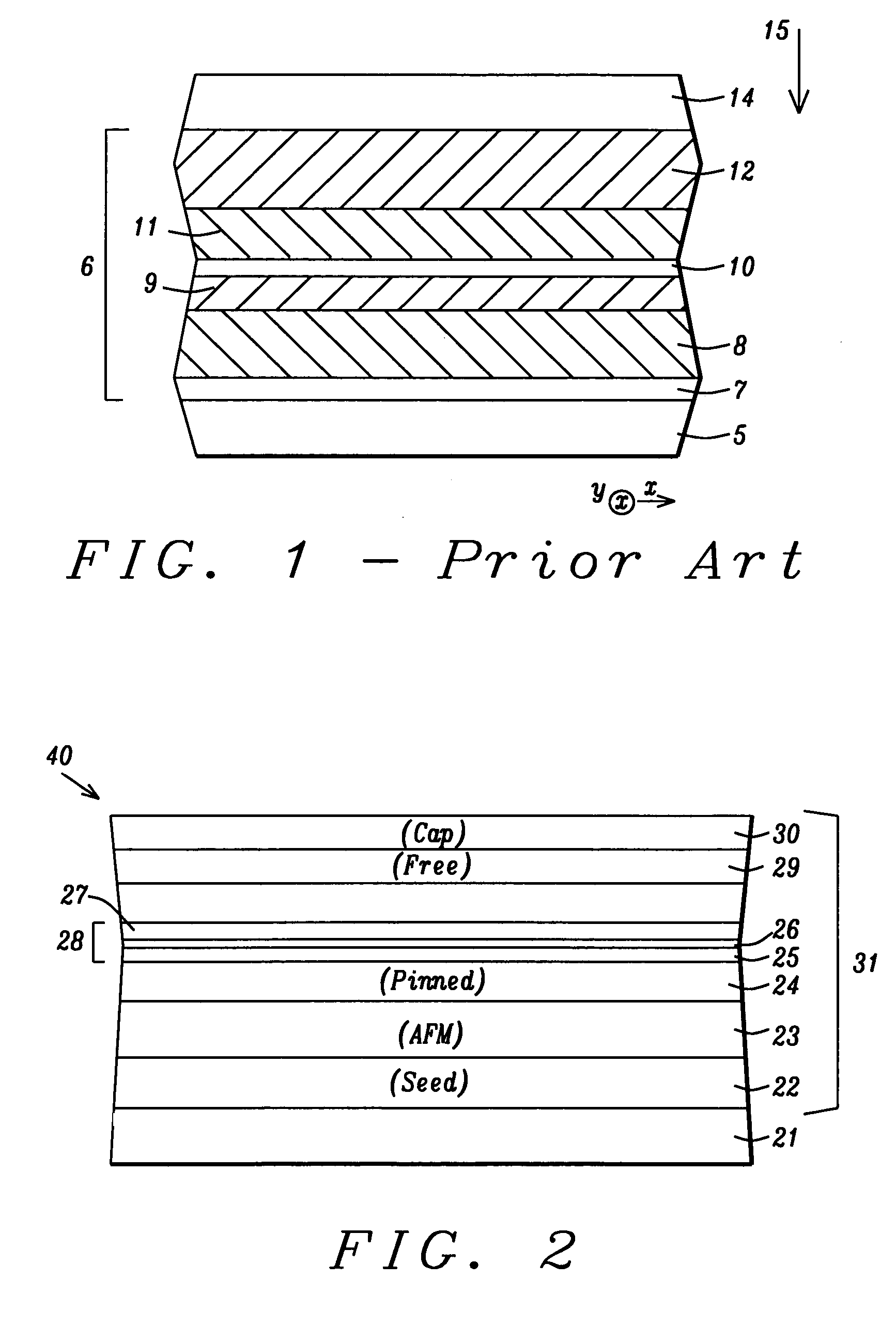
[0021]The present invention is a high performance TMR sensor having a barrier layer comprised of a Mg / MgO / Mg stack and a method for making the same wherein the MgO layer may be formed by a natural oxidation process of the lower Mg layer. While the exemplary embodiment depicts a TMR sensor in a read head, the present invention may be employed in other devices based on a tunneling magnetoresistive element such as MRAM structures. The TMR sensor may have a bottom spin valve, top spin valve, or multilayer spin value configuration as appreciated by those skilled in the art. The drawings are provided by way of example and are not intended to limit the scope of the invention. For example, the drawings are not necessarily drawn to scale and the relative sizes of various elements may differ compared with those in an actual device.

[0022]Referring to FIG. 2, a portion of a partially formed TMR read head 40 of the present invention is shown from the plane of an air bearing surface (ABS). There ...


PUM

PropertyMeasurementUnit
pressureaaaaaaaaaa
pressureaaaaaaaaaa
thicknessaaaaaaaaaa

Abstract

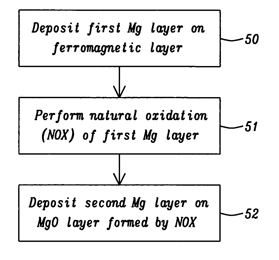
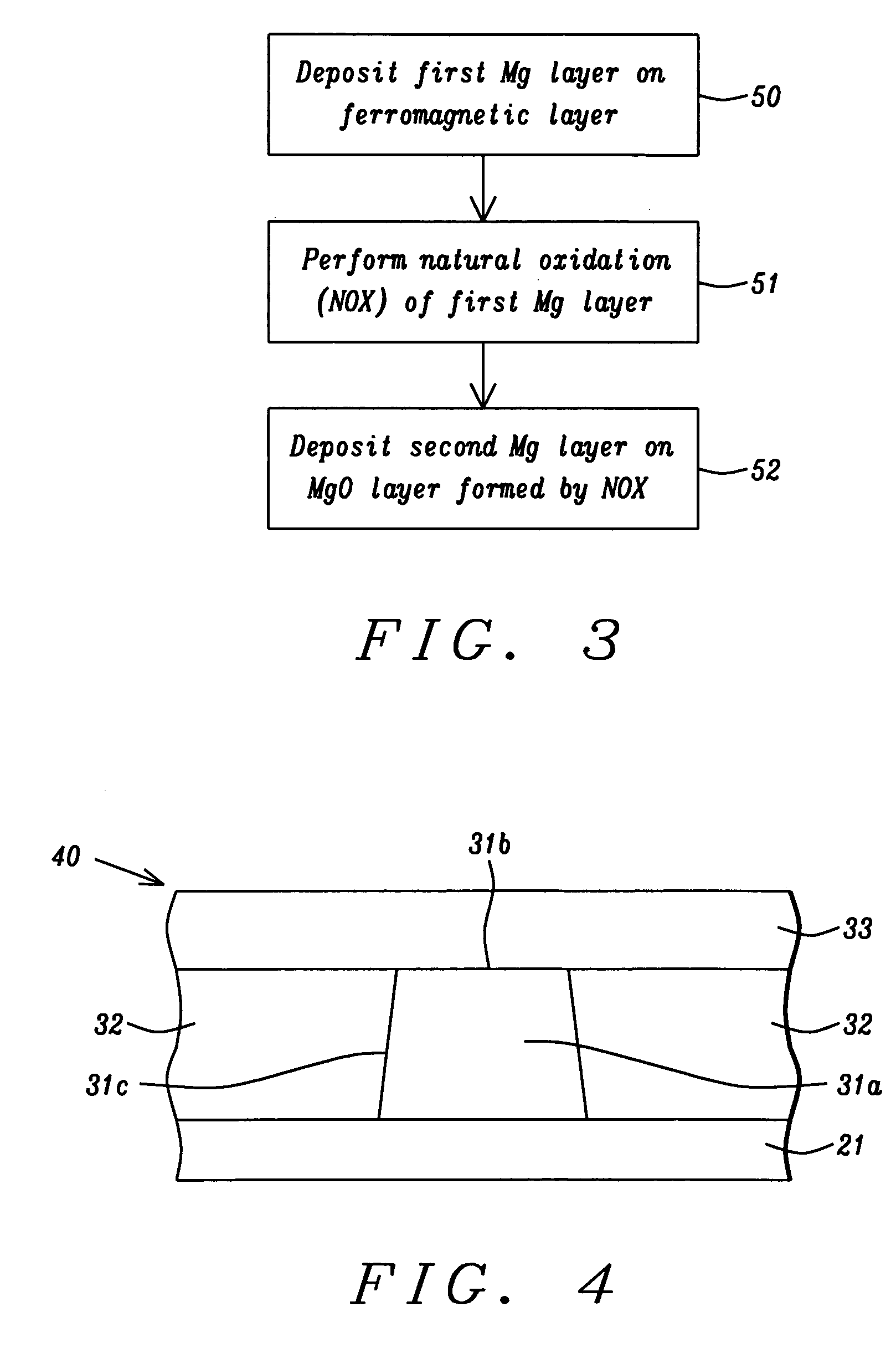
A high performance TMR sensor is fabricated by incorporating a tunnel barrier having a Mg / MgO / Mg configuration. The 4 to 14 Angstroms thick lower Mg layer and 2 to 8 Angstroms thick upper Mg layer are deposited by a DC sputtering method while the MgO layer is formed by a NOX process involving oxygen pressure from 0.1 mTorr to 1 Torr for 15 to 300 seconds. NOX time and pressure may be varied to achieve a MR ratio of at least 34% and a RA value of 2.1 ohm-um2. The NOX process provides a more uniform MgO layer than sputtering methods. The second Mg layer is employed to prevent oxidation of an adjacent ferromagnetic layer. In a bottom spin valve configuration, a Ta / Ru seed layer, IrMn AFM layer, CoFe / Ru / CoFeB pinned layer, Mg / MgO / Mg barrier, CoFe / NiFe free layer, and a cap layer are sequentially formed on a bottom shield in a read head.

Description

RELATED PATENT APPLICATIONS[0001]This application is related to the following: Ser. No. 11 / 317,388, filing date Dec. 22, 2005.FIELD OF THE INVENTION[0002]The invention relates to a high performance tunneling magnetoresistive (TMR) sensor in a read head and a method for making the same, and in particular, to a method of forming a MgO barrier between a pinned layer and free layer that improves the MR ratio and tunnel barrier uniformity while achieving a low resistance×area (RA) value.BACKGROUND OF THE INVENTION[0003]A TMR sensor serves as a memory element in magnetic devices such as Magnetic Random Access Memory (MRAM) and a magnetic read head. In FIG. 1, a TMR sensor 6 is shown as a stack of layers that has a configuration in which two ferromagnetic layers are separated by a thin non-magnetic dielectric layer. In a magnetic read head, the TMR sensor 6 is formed between a bottom shield 5 and a top shield 14. The bottom (seed) layer 7 in the TMR sensor 6 is generally comprised of one o...

Claims


Application Information

Patent Timeline
Patent Type & Authority Patents(United States)
IPC IPC(8): C23C14/34
CPCB82Y10/00B82Y25/00B82Y40/00G01R33/093G01R33/098G11B5/3906H01F10/3254H01F41/307H01L43/12G11B5/3909Y10T428/1114H01F10/3272Y10T428/1143H10N50/01
Inventor ZHAO, TONGZHANG, KUNLIANGWANG, HUI-CHUANCHEN, YU-HSIALI, MIN
Owner HEADWAY TECH INC
Learn More