Electrical machine with electronic power unit for conversion

a technology of electronic power unit and electric machine, which is applied in the direction of dynamo-electric components, dynamo-electric components, and control/drive circuits. it can solve the problems of limiting the achievable frequency range to 0-13 of the input frequency, increasing the rotary speed of the turbine, and increasing the size and cost of the equipment. it can reduce the number of necessary components, reduce the number of thyristors, and save spa

Inactive Publication Date: 2010-08-24
ALSTOM TECH LTD
View PDF14 Cites 10 Cited by
  • Summary
  • Abstract
  • Description
  • Claims
  • Application Information

AI Technical Summary

Benefits of technology

[0022]According to a first embodiment of the invention, the matrix converter is additionally characterised in that the bus bars are arranged substantially orthogonal to the grid bus bars. The perpendicular arrangement of the two sets of bus bars allows a surprisingly simple and efficient connectivity and an ideal spatial arrangement of the individual elements of the matrix converter. Typically, there is provided m / n bus bars and 2n grid bus bars.
[0036]So far, in accordance with the state-of-the-art, typically the alternating current generated in the stator of a generator is guided to a space consuming cubicle having a matrix converter and which is located in a separate area of the industrial hall of the generator. Such a cubicle for accommodating a matrix converter as for example proposed in the above-mentioned DE-A-100 51 222 may, for the case of a high-power generator (e.g., 150 MW machine) easily comprise around 1000 thyristors which necessitate a cubicle which is, e.g., 2 m high and 40 m long. So one can see that for a high-power generator such a matrix converter may be very space consuming. As already proposed in the application PCT / EP2006 / 060617, it is in principle possible to reduce the number of thyristors for example by providing a multistage matrix converter. Such a topology would not only reduce the number of necessary high-power switching elements, but it will also reduce the space requirements.
[0037]It has now been found that the one very appropriate location for a cubicle with a matrix converter, or generally of an electronic power unit for conversion, is right laterally adjacent to the stator, such that the connectors connecting the electronic power unit to the end windings of the stator are as short as possible in order to keep dissipation and stray field problems at a minimum.
[0043]Preferably, the housing comprises a top opening, and the cubicle comprises at least one feed-through openings in its bottom wall, and the generator phase conductors are mounted such as to, with their vertical parts, lead through the feed through opening of the cubicle to input connections of the matrix converter. The generator phase conductors or groups of generator phase conductors are preferably located such as to make sure that they are not interfering with each other (and / or with the walls of the cubicle) such as to keep insulation requirements as low as possible. Preferably, the matrix converter comprises a first generator stage in which m / k of the m phases of the polyphase alternating current of the generator are controlled in k (k<m) stacks (generator-stacks) of switchable elements (e.g., thyristors), and wherein groups of m / k generator phase conductors are jointly guided upwards (but still isolated from each other) to generator-stacks for feeding into the matrix converter.

Problems solved by technology

In power generation, at a specified output, an increase of the rotary speed of a turbine is associated with a decrease in size and costs.
As the output increases, the use of gearing arrangements becomes increasingly difficult due to reliability reasons.
A reduction of the losses would above all have a bearing on investment costs because cooling accounts for a substantial part of the total costs of the converter.
However, the use of 3-phase cyclo-converters limits the achievable frequency range to 0-⅓ of the input frequency.
Exceeding the ⅓ limit in frequency ratio results in a strongly unbalanced operation, in which case each single phase cyclo-converter should be designed for more than ⅓ of the full power.
This provides the option of establishing any desired connections between the input phases and the output phases; however, at the same time, it has a disadvantage in that certain switching states of the matrix must be excluded since otherwise, for example, a short circuit would result.
While being of high efficiency and versatility, the common concept of a matrix converter and its mode of operation generally suffers from weaknesses for certain applications with respect to harmonic distortion and with respect to possible frequency ratios.
So one can see that for a high-power generator such a matrix converter may be very space consuming.
Since the matrix converter, or more generally the electronic power unit, is located directly adjacent to the generator, vibrational problems may occur.

Method used


Image

  • Electrical machine with electronic power unit for conversion
  • Electrical machine with electronic power unit for conversion
  • Electrical machine with electronic power unit for conversion

Examples


Embodiment Construction

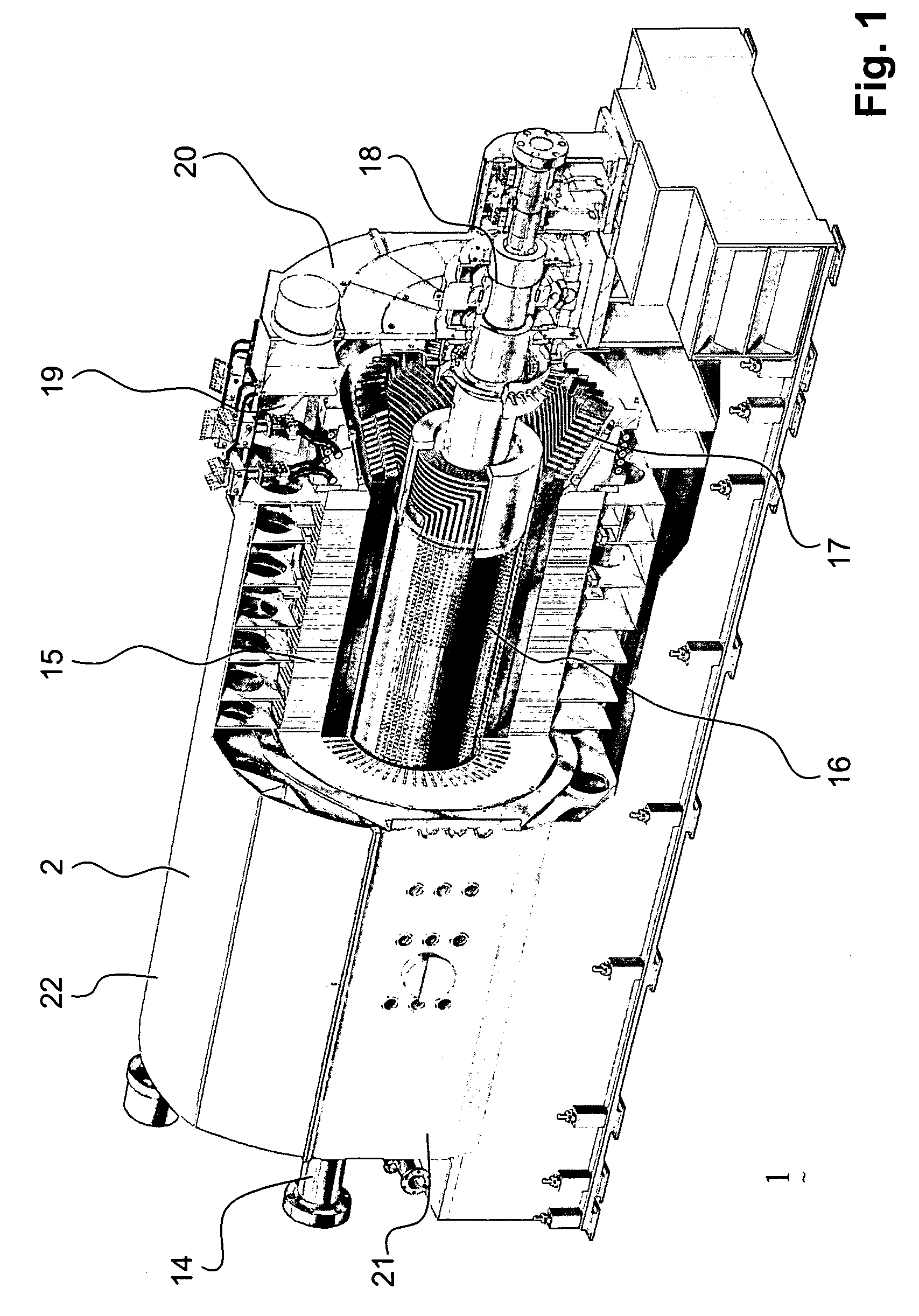
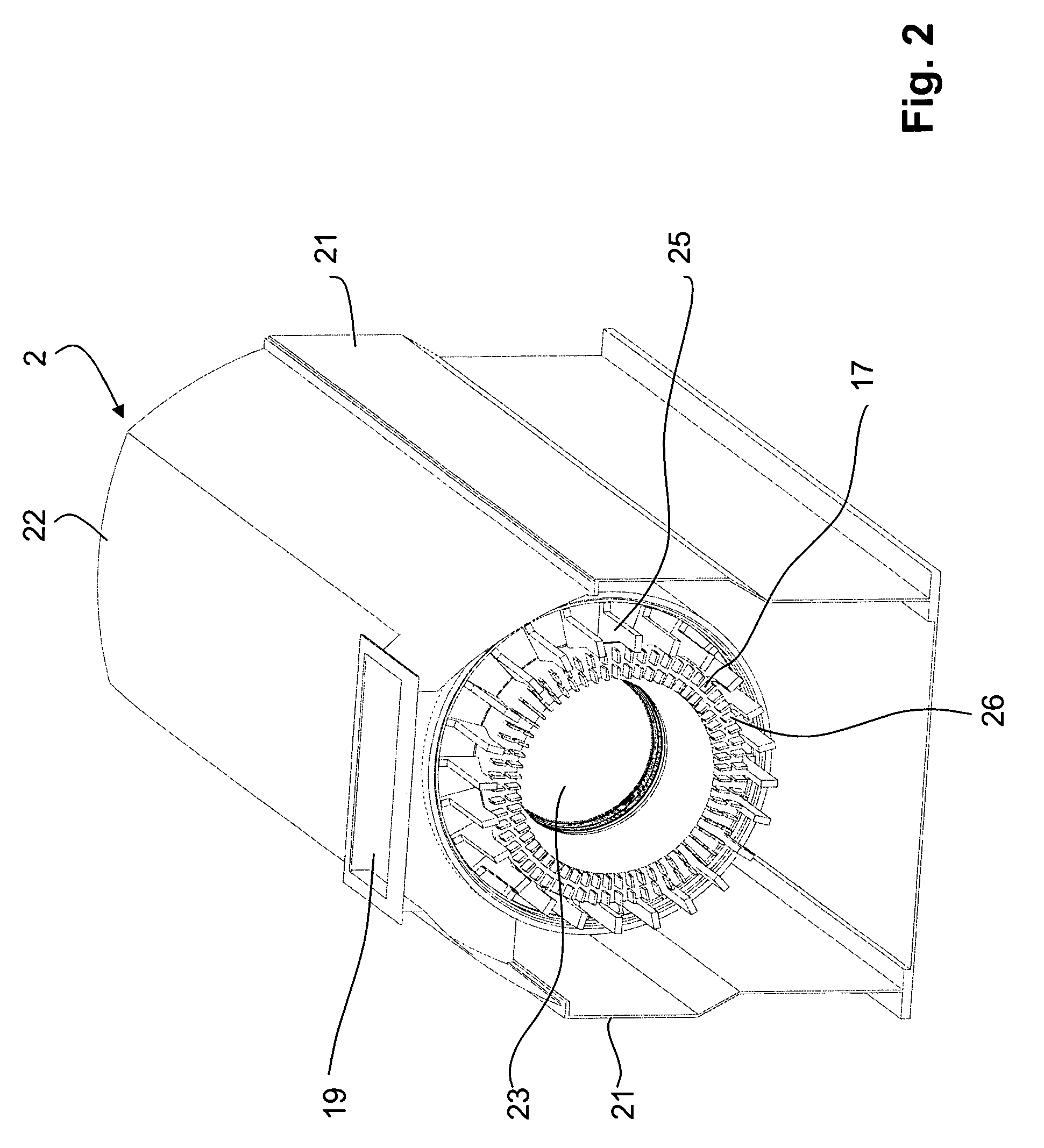
[0056]Referring to the drawings, which are for the purpose of illustrating the present embodiments of the invention and not for the purpose of limiting the same, FIG. 1 shows a generator 1 according to the state of the art, in which a stator 15 is mounted in a housing 2. In the bore of the stator the rotor 16 of the generator is mounted, wherein the rotor is carried by bearings 18, located on both sides of the stator. The rotor 16 extends into a shaft 14, and on one side the shaft 14 is coupled to, for example, a turbine providing the mechanical energy for rotation of the rotor.

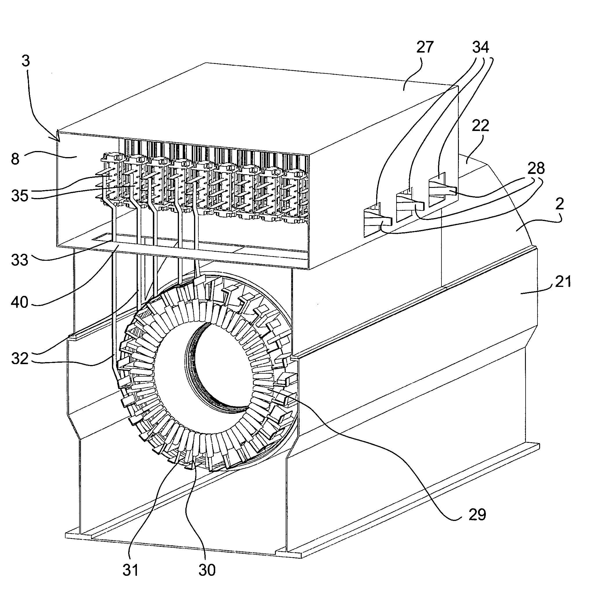
[0057]On each terminal side, the stator includes free stator-windings, the end-windings 17, and the output current of the stator generated due to the rotation of the rotor is guided to the grid by first collecting it by the so-called phase rings or circular rings and by then guiding the current out of the housing via the top opening 19.

[0058]The housing is generally of elongate shape and includes sidewalls 21...


PUM


Abstract

A matrix converter for the conversion of a polyphase alternating current into a desired alternating output current in which m phases of the polyphase alternating current are converted into alternating output current with n (n<m) phases of a load by a multiple number of controllable bidirectional switches. The converter includes at least one stage, and in that at least one stage of the converter each phase of the polyphase alternating current is controlled by a controllable bidirectional switch. The at least one stage of the converter is formed by a two-dimensional array of stage stacks of switching elements which stage stacks are arranged substantially parallel to each other along a stack direction perpendicular to the plane of the matrix converter, and wherein the input of the stage stacks is provided by bus bars located on one side of the stage stacks.

Description

[0001]This application claims priority under 35 U.S.C. §119 to European patent application no. 07104474.7, filed 20 Mar. 2007, the entirety of which is incorporated by reference herein.BACKGROUND[0002]1. Field of Endeavor[0003]The disclosure pertains to an electrical machine having a stator and a rotor rotatably and coaxially mounted therein, preferably a generator, and a housing within which the stator and the rotor are substantially located, and an electronic power unit for conversion of polyphase alternating current.[0004]2. Brief Description of the Related Art[0005]In power generation, at a specified output, an increase of the rotary speed of a turbine is associated with a decrease in size and costs. Efficiency, too, can be improved. So far, power generation turbines up to 70 MW are connected to generators by way of gearing arrangements, so as to allow operation at higher turbine rotary speeds. As the output increases, the use of gearing arrangements becomes increasingly difficu...

Claims


Application Information

Patent Timeline
Patent Type & Authority Patents(United States)
IPC IPC(8): H02K11/00H02M5/00H02M5/32
CPCH02K11/0073H02M5/272H02M5/297H02M7/003H02P27/04H02K11/33
Inventor LACAZE, ALAIN
Owner ALSTOM TECH LTD
Why Eureka
Try Eureka