Hot melt application system

a technology of hot melt and application system, which is applied in the direction of liquid/solution decomposition chemical coating, electric/magnetic/electromagnetic heating, and magnetic body, etc., can solve the problems of high fluid pressure, electrical energy, and material start-up delay of the system,

Inactive Publication Date: 2010-08-31
LASKO STEPHEN B
View PDF1 Cites 20 Cited by
  • Summary
  • Abstract
  • Description
  • Claims
  • Application Information

AI Technical Summary

Problems solved by technology

The startup of the system requires a delay for the material in the reservoir to melt.
Flow resistance of viscous materials in the heated delivery hoses requires high fluid pressures.
Maintaining a reservoir of hot material, pressure pumping for distant delivery, and maintaining heat in the delivery system elements are all wasted electrical energy.
Localized over temperature spots are a result of resistance element heating not being able to adequately expose the majority of the material to a heat conduction element that is not in excess of the target temperature.
Hot delivery elements, particularly delivery hoses, are a costly replacement item.
Material changes are difficult and time consuming.
Higher melting temperature materials [400° to 450° F.] are particularly difficult to apply in the system.

Method used


Image

  • Hot melt application system
  • Hot melt application system
  • Hot melt application system

Examples


Embodiment Construction

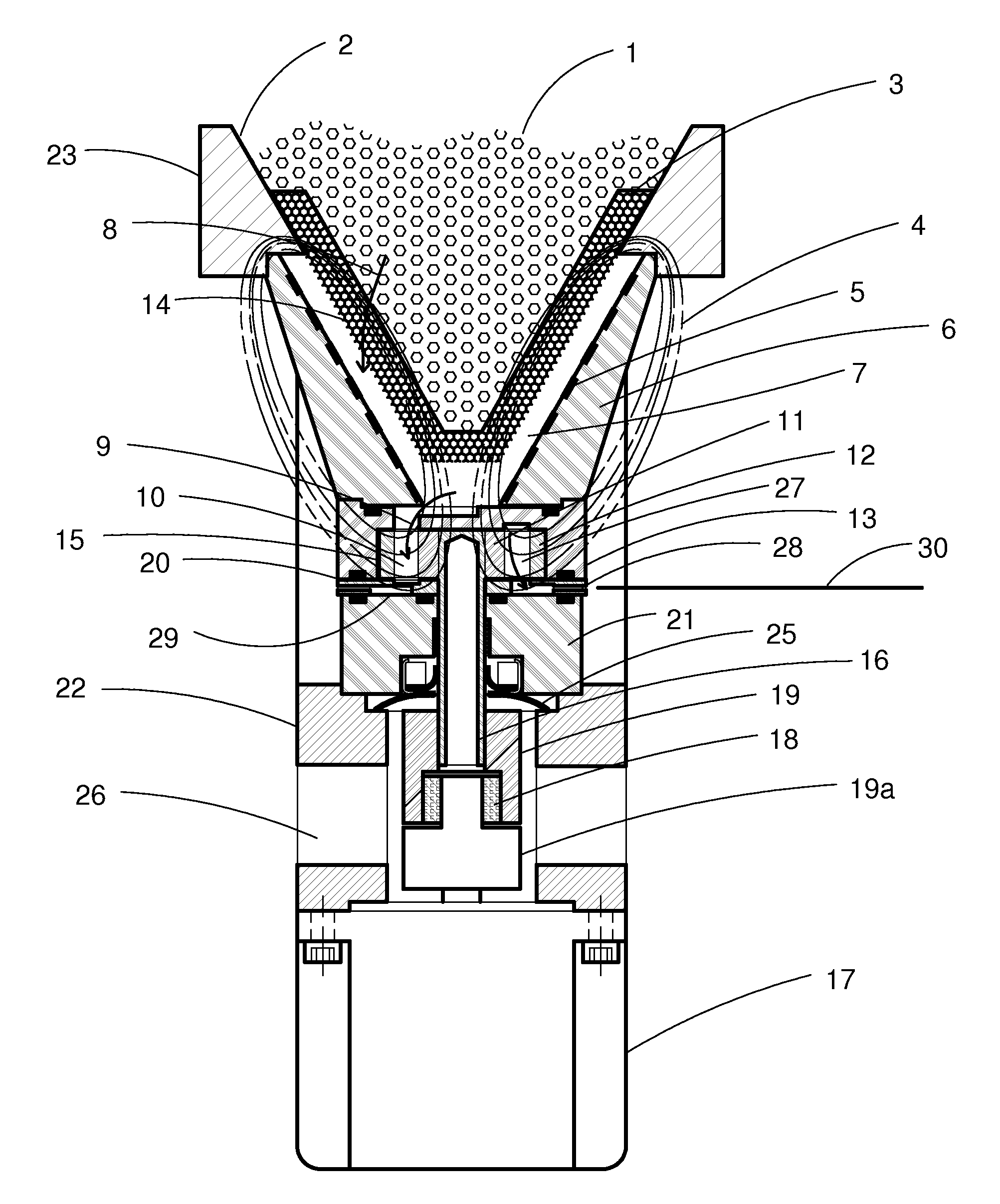
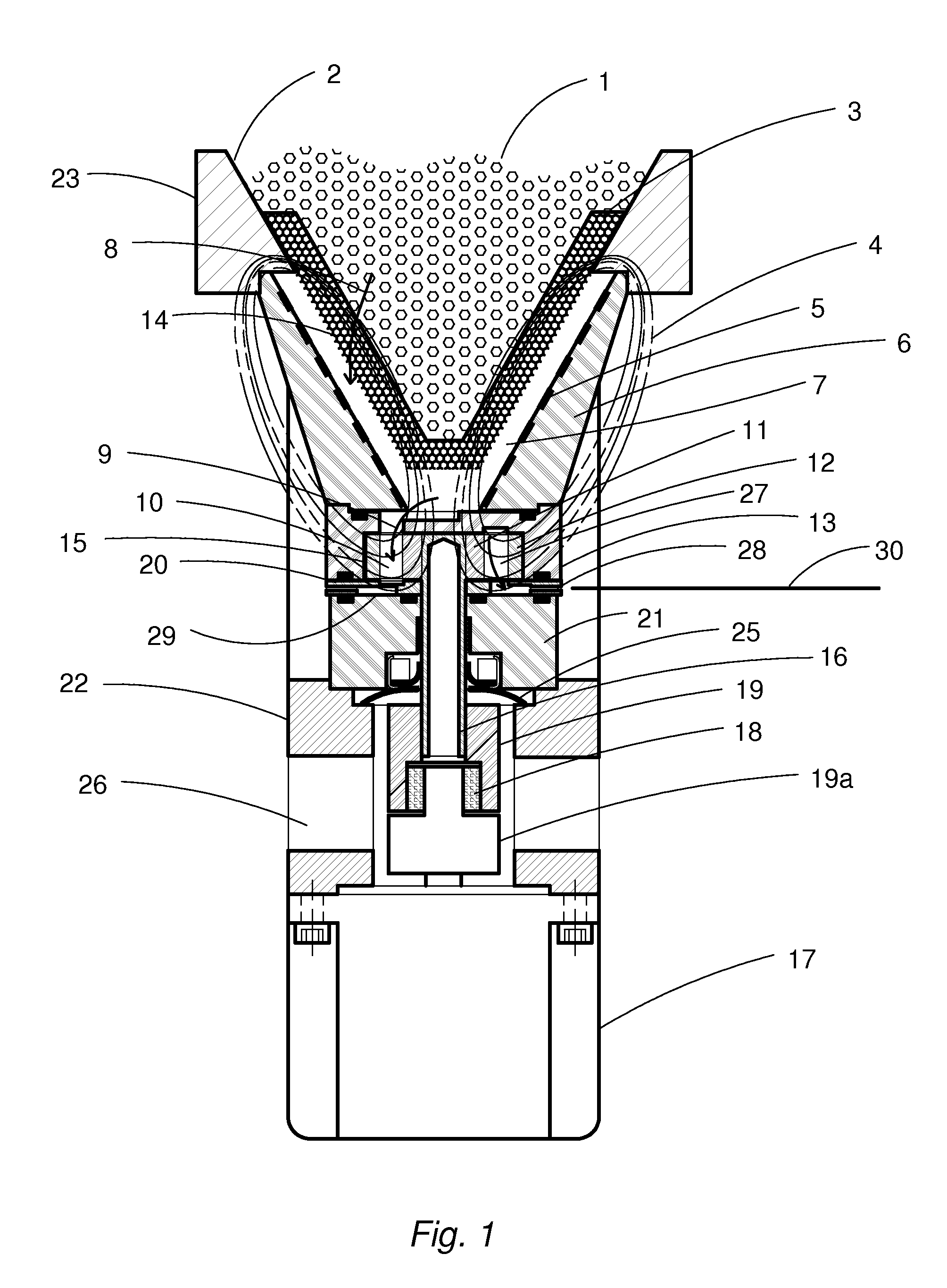
[0009]FIG. 1 is a partial cross section of the apparatus of the invention. Thermoplastic polymer pellets 1 migrate by gravity flow to the apex of hopper 2 where they contact thermal susceptor 3. The susceptor is heated by the magnetic field 4 of inductor coil 5. The interactions of these elements are described in detail in Lasko U.S. Pat. No. 5,584,419.

[0010]Inductor coil 5 is cast in a ridged high temperature epoxy form 6 with its elongated surface exposed and spaced to transmit a uniform heat in susceptor 3. This susceptor is formed in the shape of a cone from metal foam or perforated metal sheet with a defined open space to maximum surface area ratio. Pellets 1 in contact with the susceptor receive heat by conduction from the susceptor and migrate through the spaces in the susceptor as they liquefy and exit into annulus 7 between susceptor 3 and inductor coil 5. Material transit depicted by arrow 8 requires only approximately two seconds of residency time in susceptor 5 to attain...


PUM

PropertyMeasurementUnit
melting temperatureaaaaaaaaaa
meltingaaaaaaaaaa
magnetic fieldaaaaaaaaaa

Abstract

Hot melt adhesive pellets are melted and pressure pumped in a controlled application pattern on the substrate at the application site. The high frequency power supply, induction heated melting susceptor, pressure pump, and pattern control electronics are all contained in a single unit within adhesive projection distance.

Description

CROSS-REFERENCE TO RELATED APPLICATIONS[0001]This application claims the benefits of provisional application Ser. No. 60 / 889771 filed Feb. 14, 2007, in the United States Patent & Trademark Office.FIELD OF THE INVENTION[0002]A method and apparatus for delivering melted material. The invention utilizes an induction-heated susceptor attached to a gerotor pump to melt and apply thermoplastic polymer materials.BACKGROUND OF THE INVENTION[0003]Hot melt adhesive materials are currently applied by melting pellets or slats in a resistance heated reservoir, pumping the hot liquid with a resistance heated pump through a resistance heated hose, to heated valves and nozzles at the application point. Each of these individual zone temperatures are monitored and controlled. The startup of the system requires a delay for the material in the reservoir to melt. Flow resistance of viscous materials in the heated delivery hoses requires high fluid pressures.[0004]Maintaining a reservoir of hot material,...

Claims


Application Information

Patent Timeline
Patent Type & Authority Patents(United States)
IPC IPC(8): H05B6/02B29C35/08
CPCB05C11/1042B29B13/022B29K2105/0097
Inventor LASKO, BERNARD
Owner LASKO STEPHEN B
Why Eureka
Try Eureka