Microengineered vacuum interface for an ionization system

a vacuum interface and micro-engineered technology, applied in the field of mass spectrometry, can solve the problems of large, complex and expensive, unnecessary orifices and chambers, and reduce the size and pumping requirements of vacuum interfaces, so as to reduce orifice and channel sizes and reduce the size and pumping requirements

Active Publication Date: 2010-08-31
MICROSAIC SYST
View PDF23 Cites 36 Cited by
  • Summary
  • Abstract
  • Description
  • Claims
  • Application Information

AI Technical Summary

Benefits of technology

[0007]These problems and others are addressed by the present invention by providing key elements of an interface to a vacuum system as a miniaturised component with reduced orifice and channel sizes thereby reducing the size and pumping requirements of vacuum interfaces. The advance over prior art is achieved by using the methods of microengineering technology such as lithography, etching and bonding of silicon to fabricate suitable electrodes, skimmers, gas flow channels and chambers. In further embodiments the invention provides for a making of such components with integral insulators and vacuum seals so that they may ultimately be disposable.

Problems solved by technology

The problem is generally to couple the majority of the analyte as ions into the vacuum system, at thermal velocities, without contaminating the inlet or introducing an excess background of solvent ions or neutrals.
However, the use of macroscopic components results in orifices and chambers that are unnecessary large for nanospray emitters and that require large, high capacity pumps.
Consequently, they are complex and expensive, and require significant cleaning and maintenance.

Method used


Image

  • Microengineered vacuum interface for an ionization system
  • Microengineered vacuum interface for an ionization system
  • Microengineered vacuum interface for an ionization system

Examples


Embodiment Construction

[0018]A detailed description of the invention is provided with reference to exemplary embodiments shown in FIGS. 1 to 8.

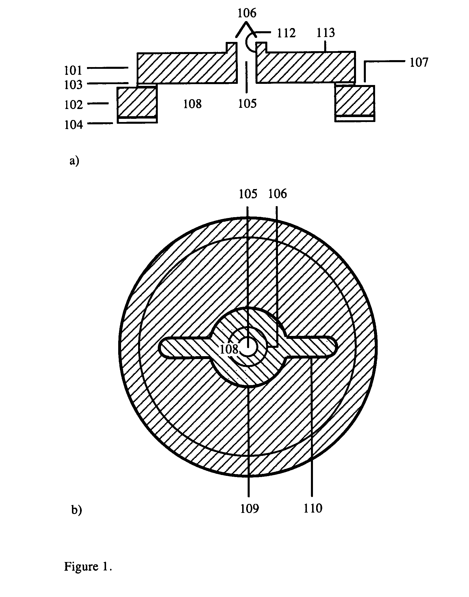
[0019]A device in accordance with the teaching of the invention is desirably fabricated or constructed as a stacked assembly of semiconducting substrates, which are desirably formed from silicon. Such techniques will be well known to the person skilled in the art of microengineering. FIG. 1 shows the first substrate, which is constructed as a multilayer. A first layer of silicon 101 is attached to a second layer of silicon 102 by an insulating layer of silicon dioxide 103. Such material is known as bonded silicon on insulator (BSOI) and is available commercially in wafer form. A further insulating layer 104 is provided on the outside of the second silicon layer.

[0020]The first silicon layer carries or defines a first central orifice 105. The interior side walls 112 of the first layer which define the orifice, include a proud or upstanding feature 106 on the outer s...


PUM

PropertyMeasurementUnit
semiconductingaaaaaaaaaa
insulatingaaaaaaaaaa
electric fieldsaaaaaaaaaa

Abstract

The invention provides a planar component for interfacing an atmospheric pressure ionizer to a vacuum system. The component combines electrostatic optics and skimmers with an internal chamber that can be filled with a gas at a prescribed pressure and is fabricated by lithography, etching and bonding of silicon.

Description

CROSS-REFERENCE TO RELATED APPLICATIONS[0001]This application claims priority to United Kingdom Patent Application No. GB0611221.3, filed Jun. 8, 2006, and United Kingdom Patent Application No. GB0620256.8, filed Oct. 12, 2006, which are expressly incorporated herein by reference and made a part hereof.FEDERALLY SPONSORED RESEARCH OR DEVELOPMENT[0002]Not applicable.TECHNICAL FIELD[0003]This invention relates to mass spectrometry, and in particular to the use of mass spectrometry in conjunction with liquid chromatography or capillary electrophoresis. The invention more particularly relates to a microengineered interface device for use in mass spectrometry systems.BACKGROUND OF THE INVENTION[0004]Electrospray is a method of coupling ions derived from a liquid source such as a liquid chromatograph or capillary electrophoresis system into a vacuum analysis system such as a mass spectrometer (Whitehouse et al. 1985; U.S. Pat. No. 4,531,056). The liquid is typically a dilute solution of a...

Claims


Application Information

Patent Timeline
Patent Type & Authority Patents(United States)
IPC IPC(8): H01J49/04
CPCH01J49/0018H01J49/067Y10T408/03
Inventor SYMS, RICHARDMOSELEY, RICHARD WILLIAM
Owner MICROSAIC SYST
Why Eureka
Try Eureka