Optical sensor, optical current sensor and optical voltage sensor

a voltage sensor and current sensor technology, applied in the field of optical sensors, can solve the problems of difficult to improve the response speed, the modulation power increases, and the inability to apply the modulation degree calculation method to a dc, and achieve the effects of short rise time, simple constitution and high response speed

Inactive Publication Date: 2010-08-31
THE TOKYO ELECTRIC POWER CO INC
View PDF47 Cites 15 Cited by
  • Summary
  • Abstract
  • Description
  • Claims
  • Application Information

AI Technical Summary

Benefits of technology

[0016]Therefore, an object of the present invention is to provide a simple constitution together with an easy adjustment of zero point and an easy calibration of output by realizing a light intensity detection method in which information is indicated by using the intensity of a high speed (high response speed, short rise time) received signal without using the carrier signal.
[0020]In accordance with the present invention, a light intensity detection method in which information is indicated by using the intensity of a high speed (high response speed, short rise time) received signal without using the carrier signal is realized. Therefore, a significantly simple constitution together with an easy adjustment of zero point and an easy calibration of output by realizing is achieved. As a result, an advantage is obtained in which it is possible to measure a wide range of current and voltage from a DC to a high frequency AC.

Problems solved by technology

However, with respect to these necessities, there are problems such as an application of technologies developed for AC, a method of setting a zero point (a method of setting an output 0 when a measured current is 0), a method of adjusting the sensitivity (adjusting a reset value of the sensitivity of output) and moreover the stabilization of set values.
However, it is not possible to apply the method of calculating the degree of modulation to a DC.
As described above, a Sagnac interferometer has the following problems.i) A delicate and complex optical system is necessary.ii) A complex signal operation circuit is necessary.iii) It is difficult to improve a response speed because complex operations such as generating the carrier signal and a modulation and demodulation are conducted.
However, in this case, the modulation power increases and pressure on the signal operation circuit increases too.

Method used


Image

  • Optical sensor, optical current sensor and optical voltage sensor
  • Optical sensor, optical current sensor and optical voltage sensor
  • Optical sensor, optical current sensor and optical voltage sensor

Examples


Embodiment Construction

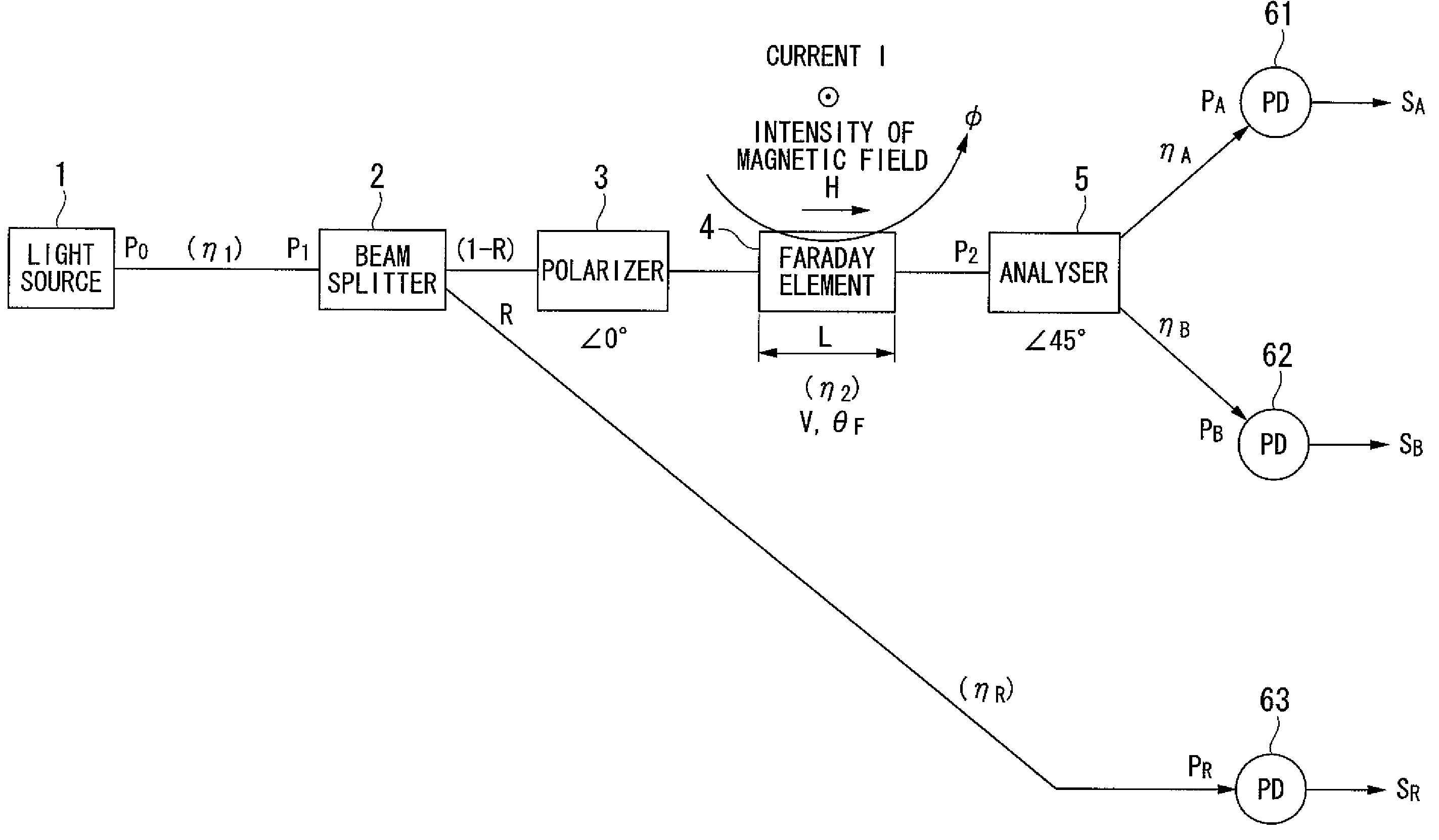
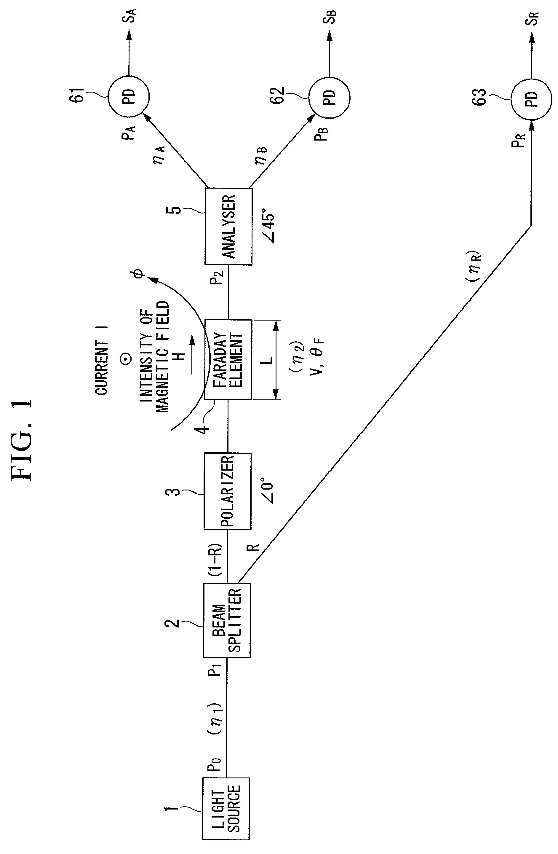
[0029]FIG. 1 is a drawing which shows a principle constitution of the present invention.

[0030]In FIG. 1, 1 is a light source, 2 is a beam splitter, 3 is a light polarizer, 4 is a Faraday cell, 5 is an analyser, and 61-63 are light receiving elements such as photodiodes (PD).

[0031]Now, a separation ratio of the beam splitter 2 is R, a transmission efficiency regarding a quantity of light is η, a length of the Faraday cell 4 is L, a Faraday rotation angle is θ, a Verdet constant is V and an intensity of a magnetic field generated by a current I is H. Followings are defined.

|2θF|F=VHL=VI  (1)

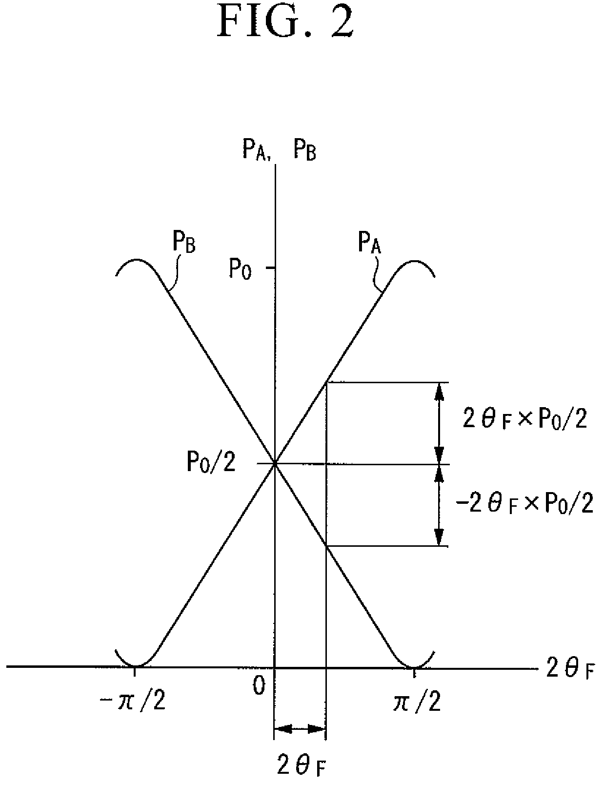
Quantity of light PA, PB and PR which reach the light receiving elements 61-63 are shown by using the following equations.

PA=η1*η1*ηA*(1−R)(1 / 2)P0(1+2θF)  (2)

PB=η1*η2*ηB*(1−R)(1 / 2)P0(1-2θF)  (3)

PR=η1*ηR*R*P0  (4)

[0032]In an ideal case, the following equations are applied.

R=0  (5)

η1=η2=ηR=ηA=ηB=1  (6)

[0033]Therefore, the following equations are obtained by applying equations (5) and (6) to equations...


PUM


Abstract

A simple constitution together with an easy calibration of output by realizing a fast light intensity detection method is realized without using the carrier signal.An optical sensor, including: a sensor to which light from a light source is lead, and by which light intensity of the light is modulated based on a physical value; light receiving elements 61 and 62 receiving two elements of divided light PA and PB having polarized waves which are orthogonally crossing each other; a variable optical attenuator operating light which is received by the light receiving elements 61 and 62; and a variable amplifier operating output signals from the light receiving elements 61 and 62, wherein both a zero point of a sensor output and sensitivity are calibrated based on a light attenuation factor or an amplification factor which is adjusted when a physical value is detected by calculating a ratio between a sum and a difference of outputs of the light receiving elements 61 and 62.

Description

RELATED APPLICATIONS[0001]This application relates to U.S. patent application Ser. No. 11 / 817,955 filed on Sep. 6, 2007 and entitled “INTENSITY MODULATION TYPE OPTICAL SENSOR AND OPTICAL CURRENT / VOLTAGE SENSOR.”BACKGROUND OF THE INVENTION[0002]1. Field of the Invention[0003]The present invention relates to optical sensors, especially an optical current sensor and an optical voltage sensor which can measure a wide range of current and voltage from a DC to a high frequency AC.[0004]2. Description of the Related Art[0005]In recent years, developments and practical applications of an optical fiber AC sensor by using the Faraday effect have been proposed (for example, see non-patent document 1: Kurosawa “Development and Application of Optical Fiber Current Sensor”, Journal of the Institute of Electrostatics Japan, vol. 28 No. 5 (p. 251-257), 2004). Along with the development of the optical fiber AC sensor, it has been expected to realize an optical fiber DC sensor that can be applied to ...

Claims


Application Information

Patent Timeline
Patent Type & Authority Patents(United States)
IPC IPC(8): G01R31/00
CPCG01R15/247
Inventor KUROSAWA, KIYOSHISHIRAKAWA, KAZUOMI
Owner THE TOKYO ELECTRIC POWER CO INC
Why Eureka
Try Eureka