
Wireless communication apparatus

a communication apparatus and wireless technology, applied in data switching networks, modulated carriers, frequency-division multiplex details, etc., to achieve the effect of improving reliability, reducing load of error correction decoding processing at the final-stage receiver, and improving signal reliability

Active Publication Date: 2010-08-31
PANASONIC INTELLECTUAL PROPERTY CORP OF AMERICA
View PDF6 Cites 6 Cited by
  • Summary
  • Abstract
  • Description
  • Claims
  • Application Information

AI Technical Summary

Benefits of technology

The present invention provides a wireless communication apparatus that can correct error flexibly without wasting consumed resources while maintaining the improvement of reliability resulted from error correction. The apparatus subjects a received signal to error correction decoding processing and transmits a soft decision value obtained by re-coding the signal after the error correction decoding processing as a relay signal, when error is detected in the hard decision bits after the error correction decoding processing. This soft decision value is not "1" or "−1" but a decision value having an intermediate value. The apparatus can also relay and transmit the hard decision value as a relay signal when error is detected. This helps to improve the reliability of the received signal.

Problems solved by technology

On the other hand, when any error is detected in this case, the relaying and transmission processings are not performed or the hard decision bits before the error correction decoding are relayed and transmitted.

Method used


Image

  • Wireless communication apparatus
  • Wireless communication apparatus
  • Wireless communication apparatus

Examples


first embodiment

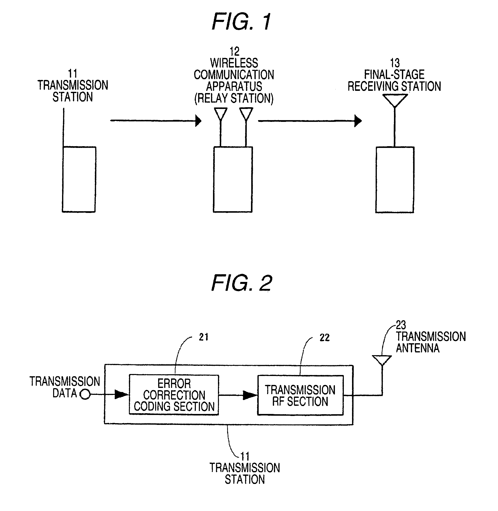
[0078]FIG. 1 is a diagram showing the system configuration of a wireless communication apparatus (relay station) for explaining the embodiment of the invention. A signal transmitted from a transmission station 11 is relayed by a wireless communication apparatus (relay station) 12 and transmitted to a final-stage receiving station 13.

[0079]FIG. 2 shows a schematic block diagram of the transmission station 11. The error correction coding section 21 of the transmission station 11 subjects transmission data to the error correction coding, then a transmission RF section 22 modulates the signal after the error correction coding and a transmission antenna 23 transmits the modulated signal to the relay station.

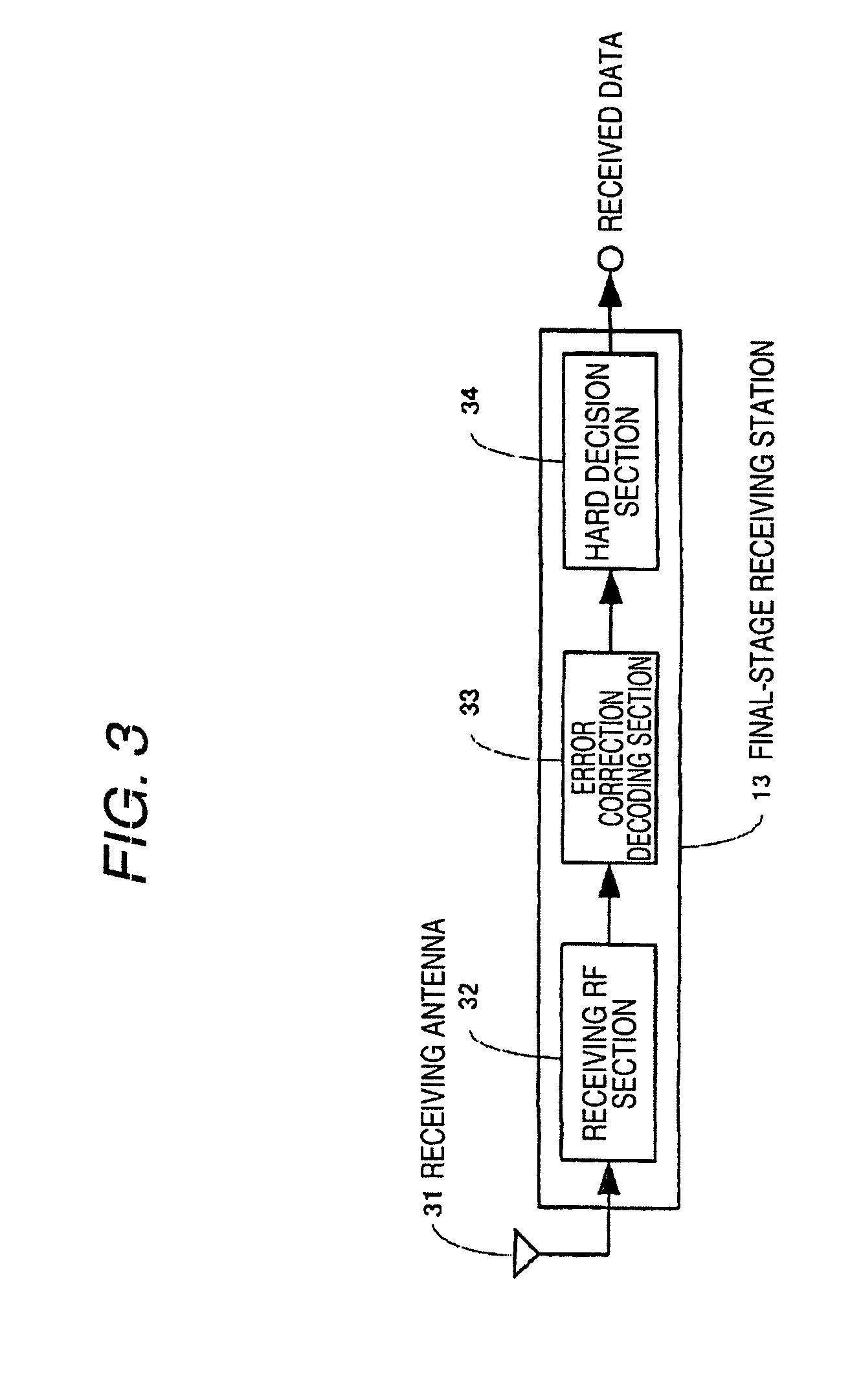
[0080]FIG. 3 shows a schematic block diagram of the final-stage receiving station 13. Radio wave transmitted from the relay station is received by a receiving antenna 31, then demodulated by a receiving RF section 32 and inputted to an error correction decoding section 33. The error c...

second embodiment

[0092]FIG. 9 is a diagram showing the system configuration of a wireless communication apparatus (relay station) according to the second embodiment of the invention. Data channel transmitted from a transmission station 11 is relayed by a wireless communication apparatus (relay station) 103 and transmitted to a final-stage receiving station 13. The final-stage receiving station 13 transmits iteration number instruction information to the relay station 103.

[0093]FIG. 10 shows a schematic block diagram of the wireless communication apparatus (relay station) 103 of this embodiment. The wireless communication apparatus (relay station) 103 includes a receiving antenna 41 for receiving signals transmitted from the transmission station, a receiving RF section 42 for high-frequency amplifying the received signal, an interaction number instruction information detecting section 101 for detecting iteration number instruction information from the received signal, an interaction number decision s...


PUM


Abstract

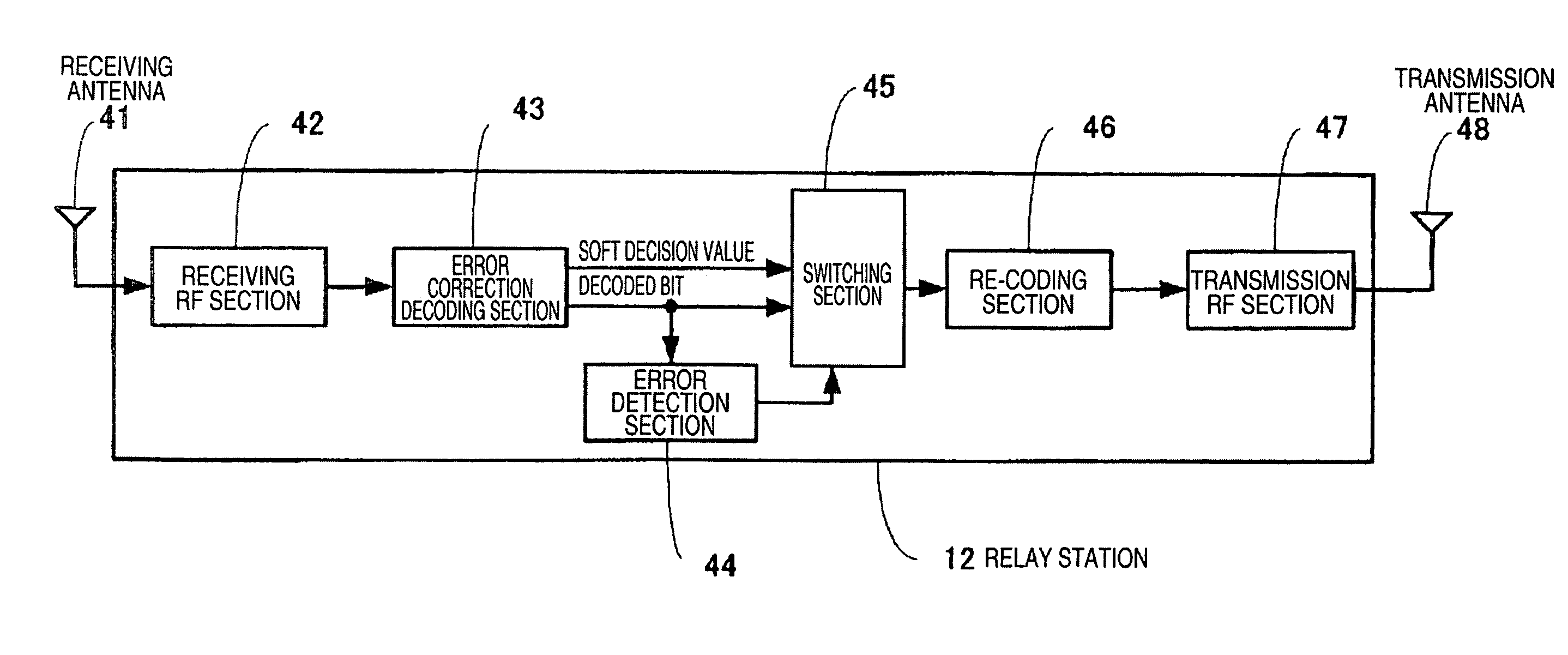
An object of the invention is to provide a wireless communication apparatus which can correct error flexibly without wasting consumed resources while maintaining the improvement of reliability resulted from error correction. The wireless communication apparatus (relay station) 12 includes a receiving antenna 41 for receiving signals transmitted from the transmission station, a receiving RF section 42 for high-frequency amplifying the received signal, an error correction decoding section 43 for subjecting the received signal to the error correction decoding processing and outputting soft decision values and decoded bits, an error detection section 44 for subjecting the signal after the error correction decoding processing to the hard decision processing to detect error of the signal subjected to the hard decision processing, a switching section 45 for switching the soft decision values and the decoded bits, a re-coding section 46 for re-coding extracted ones of the soft decision values, a transmission RF section 47 for modulating the re-coded soft decision values and a transmission antenna 48 for transmitting the signal to the receiving station.

Description

TECHNICAL FIELD[0001]The present invention relates a wireless communication apparatus having a function of relaying a signal transmitted from a transmission station to a receiving station.BACKGROUND ART[0002]FIG. 12 shows the schematic configuration of a wireless communication apparatus (hereinafter called a relay station or a repeater) 123 of a related art. The relay station 123 of the related art includes a receiving antenna 41 for receiving radio wave from a not-shown transmission station, a receiving RF section 42 for high-frequency amplifying the received signal, an error correction decoding section 43 for correcting the error of the signal caused in a transmission path and decoding the signal thus corrected, hard decision sections 121 and 122 each for determining signal error with “0” and “1”, an error detection section 44 for detecting error of the signal subjected to the hard decision processing, a switching section 45 for switching the outputs of the hard decision sections ...

Claims


Application Information

Patent Timeline
Patent Type & Authority Patents(United States)
IPC IPC(8): H03K11/00H04L25/60H04L25/64
CPCH04B7/155H04L1/0054H04L25/067H04L2001/0097H04W88/04
Inventor MIYOSHI, KENICHIHORIUCHI, AYAKO
Owner PANASONIC INTELLECTUAL PROPERTY CORP OF AMERICA
Learn More