
System and method for treating dust contained in extracted cement kiln combustion gas

a technology of combustion gas and extraction process, which is applied in the direction of sulfur compounds, separation processes, evaporation, etc., can solve the problems of increasing the quantity of harmful lead brought to cement kilns and the concentration of cement may exceed a management standard, so as to achieve efficient removal of lead and low facility and running costs

Inactive Publication Date: 2010-09-07
TAIHEIYO CEMENT CORP
View PDF12 Cites 77 Cited by
  • Summary
  • Abstract
  • Description
  • Claims
  • Application Information

AI Technical Summary

Benefits of technology

The invention aims to provide an apparatus and method for efficiently removing lead from dust in cement kiln combustion gas with low facility and running costs. The conventional methods require expensive facilities and chemicals, which increase the operation and maintenance costs. The technical effect of the invention is to provide a solution that reduces the need for expensive facilities and chemicals, thereby lowering the overall cost of removing lead from dust.

Problems solved by technology

It is noticed that chlorine, sulfur, alkali and the like cause troubles such as preheater clogging in cement manufacturing facilities, and especially chlorine has the most harmful effect, so that cement kiln chlorine bypass systems are used in order to remove chlorine by extracting a part of combustion gas from a kiln exhaust gas passage, which runs from an inlet end of a cement kiln to a bottom cyclone.
However, in recent years, recycling of waste through conversion to cement raw material or fuel has been promoted, which increases the quantity of harmful lead brought to cement kilns as the quantity of the treated waste increases.
As a result, lead concentration in cement may exceed a management standard.

Method used


Image

  • System and method for treating dust contained in extracted cement kiln combustion gas
  • System and method for treating dust contained in extracted cement kiln combustion gas

Examples


Embodiment Construction

The Best Mode to Carry Out the Invention

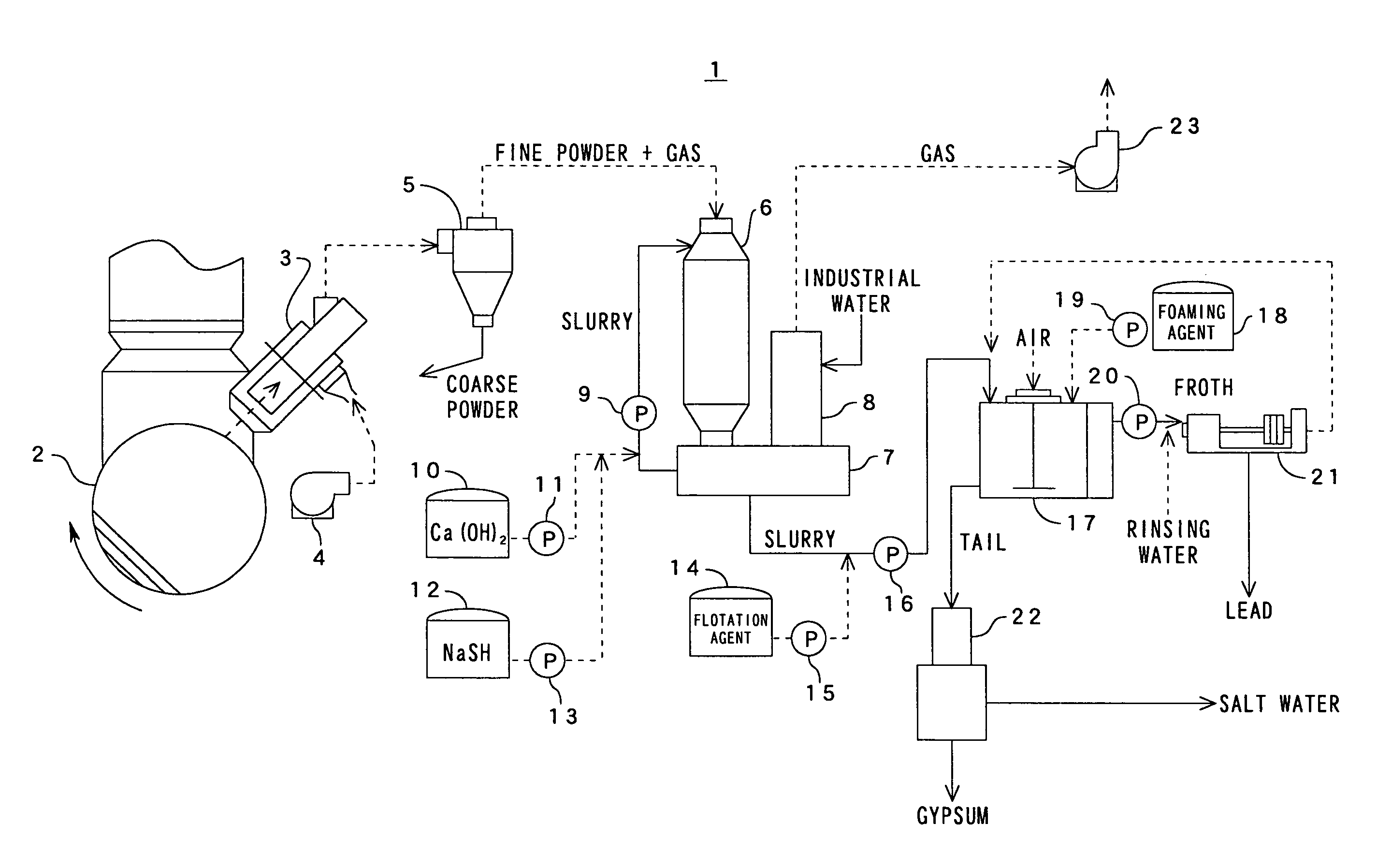
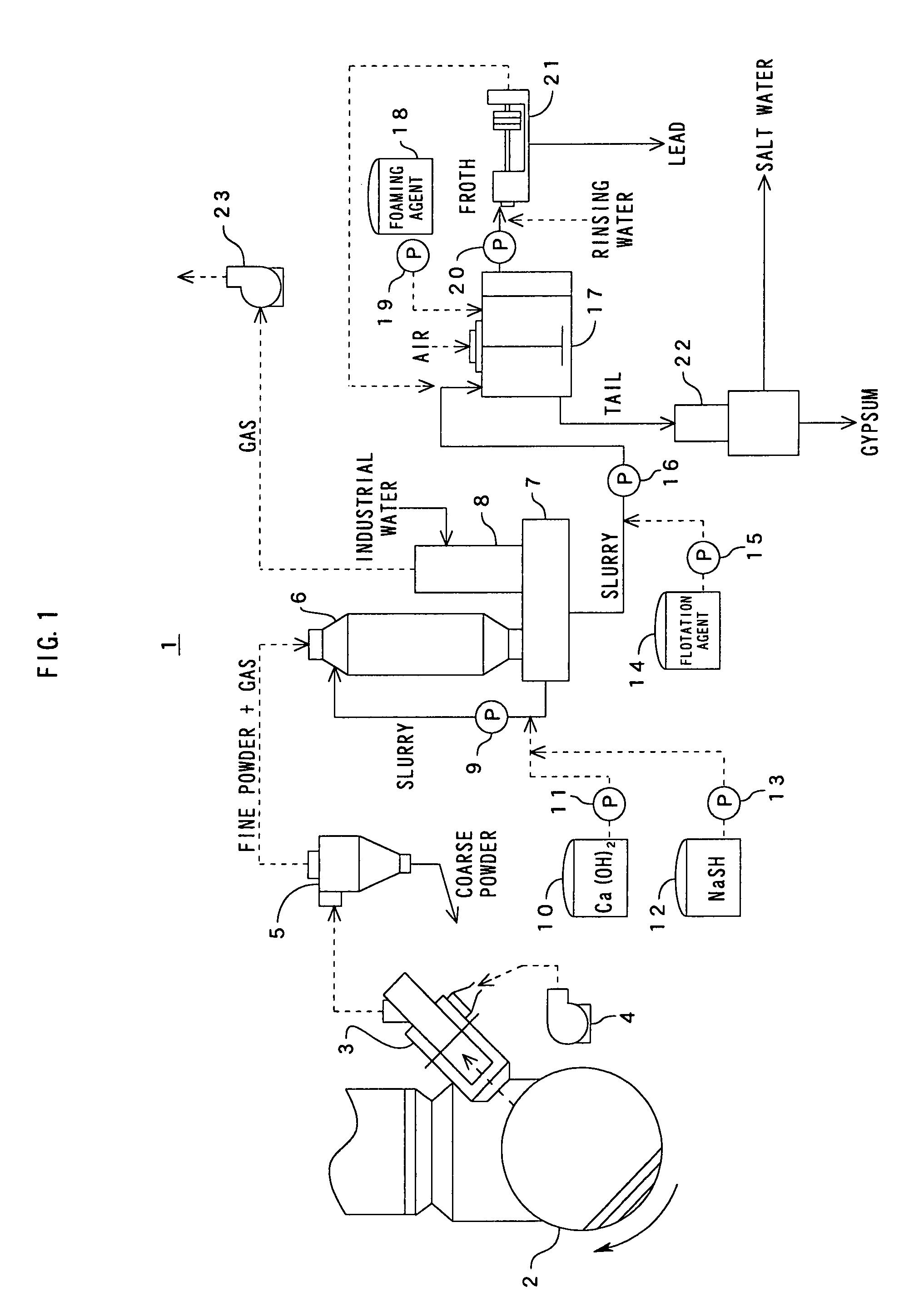
[0033]FIG. 1 shows a flowchart showing an embodiment of a system for treating dust contained in extracted cement kiln combustion gas (hereinafter referred to as “treatment system” for short) according to the present invention, this treatment system 1 comprises a probe 3 for extracting a part of combustion gas from a kiln exhaust gas passage, which runs from an inlet end of a cement kiln 2 to a bottom cyclone not shown, a cyclone 5 as a classifier for separating coarse powder from dust included in combustion gas extracted by the probe 3, a wet scrubber 6 for collecting dust of the extracted gas including fine powder discharged from the cyclone 5 in wet process, a circulation liquid tank 7 for circulating collected dust slurry to the wet scrubber 6, a tank 10 for storing Ca(OH)2 that is fed as desulfurizing agent to the wet scrubber 6, a tank 12 for storing NaSH that is fed to sulfide lead, a flotation machine 17 comprising a flotation facility ...


PUM

PropertyMeasurementUnit
pHaaaaaaaaaa
concentrationaaaaaaaaaa

Abstract

A treatment system to efficiently remove lead from dust contained in extracted cement kiln combustion gas while reducing facility and running costs. A treatment system 1 comprising: a probe 3 for extracting a part of combustion gas, while cooling it, from a kiln exhaust gas passage, which runs from an inlet end of a cement kiln to a bottom cyclone; a classifier 5 for separating coarse powder from dust contained in the combustion gas extracted by the probe 3; a wet dust collector 6 for collecting dust from the extracted gas containing fine powder discharged from the classifier 5; and devices 12, 13 for feeding sulfurizing agent for sulfurizing lead contained in the kiln exhaust gas to the wet dust collector 6, and others. From the sulfurizing-agent feeders 12, 13 are preferably added the sulfurizing agents to a circulation liquid tank 7 or a pump 9 for circulating slurry. The slurry obtained by the wet dust collector 6 is separated into froth including lead and tail side slurry including gypsum by a flotation facility 14, 17, 18.

Description

CROSS-REFERENCE TO RELATED APPLICATIONS[0001]The present application claims priority to International Application No. PCT / JP2005 / 017259 which was filed on Sep. 20, 2005 and which claims priority to Japanese Patent Application No. 2004-283397 filed Sep. 29, 2004.STATEMENT RE: FEDERALLY SPONSORED RESEARCH / DEVELOPMENT[0002]Not ApplicableBACKGROUND OF THE INVENTION[0003]1. Technical Field[0004]The present invention relates to a system and a method for treating dust contained in extracted cement kiln combustion gas, and more particularly to a method for removing chlorine, sulfur-containing compounds and the like from a part of combustion gas extracted from a kiln exhaust gas passage, which runs from an inlet end of a cement kiln to a bottom cyclone, and efficiently removing lead from dust included in the extracted combustion gas.[0005]2. Background Art[0006]It is noticed that chlorine, sulfur, alkali and the like cause troubles such as preheater clogging in cement manufacturing facilitie...

Claims


Application Information

Patent Timeline
Patent Type & Authority Patents(United States)
IPC IPC(8): B01D53/14
CPCB01D45/12B01D47/06B01D53/501B01D53/64B03D1/14C04B7/436C04B7/60B03D1/02B03D1/1462C04B7/36
Inventor SAITO, SHINICHIROOKAMURA, SOICHIROMATSURA, TSUYOSHI
Owner TAIHEIYO CEMENT CORP
Learn More