Variable magnetic coupling of rotating machinery

a rotating machinery and magnetic coupling technology, applied in the direction of machines/engines, mechanical actuated clutches, rocket engine plants, etc., can solve the problems of reducing the operability of the engine, reducing the capacity of the engine, and impractically large generators, so as to reduce vibration transfer, minimize the impact of engine capability, and reduce the chance of catastrophic failure or jamming

Active Publication Date: 2010-09-07
GENERAL ELECTRIC CO
View PDF25 Cites 61 Cited by
  • Summary
  • Abstract
  • Description
  • Claims
  • Application Information

AI Technical Summary

Benefits of technology

[0018]An advantage of the present invention is that no mechanical linkage or contact is required between the engine spools, reducing vibration transfer.
[0019]Another advantage of the present invention is that it may be internal or external to the engine.
[0020]Yet another advantage of the present invention is that it may be applied on other types of mechanical device that require variable torque transmission (e.g., hybrid automotive transmissions, etc.)
[0021]Still another advantage of the present invention is that it permits constant torque variable power coupling of one rotating shaft to another without any mechanical contact. The present invention further permits torque or power coupling without an intermediate conversion to electrical power.
[0022]A further advantage of the present invention is that it provides a method for controllably transferring mechanical power between spools of any multi-spool turbine engine which is tolerant to faults caused otherwise when mechanical gearing is used. Since there is no mechanical contact between input and output, there is less chance of catastrophic failure or jamming.
[0023]The present invention provides a system for extracting greater amounts of mechanical power from turbine engines in a manner that minimizes impact on engine capability, and can potentially enhance engine operability by variably selecting the source of the power extraction

Problems solved by technology

When operating an aircraft engine at relatively low power levels, e.g., while idly descending from altitude, extracting this additional electrical power from the engine mechanical power may reduce the ability to operate the engine properly.
The LP engine spool provides an alternate source of power transfer, however, the relatively lower speed of the LP engine spool typically requires the use of a gearbox, as slow-speed electrical generators are often larger than similarly rated electrical generators operating at higher speeds.
However, extracting this additional mechanical power from an engine when it is operating at relatively low power levels (e.g., at or near idle descending from altitude, low power for taxi, etc.) may lead to reduced engine operability.
Tapping this low-speed mechanical power source without transformation result in impractically large generators.
However, this does not provide a solution to coupling of concurrently rotating HP and LP turboshafts without using a mechanical gearbox.

Method used


Image

  • Variable magnetic coupling of rotating machinery
  • Variable magnetic coupling of rotating machinery
  • Variable magnetic coupling of rotating machinery

Examples


Embodiment Construction

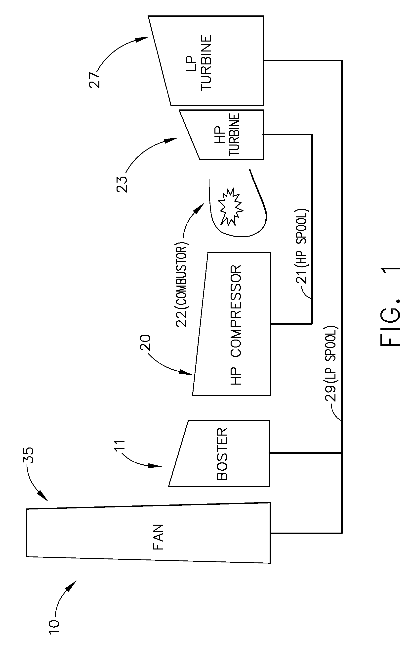
[0035]Illustrated in FIG. 1 is an exemplary generic turbofan engine 10 having a fan 35, booster 11, high-pressure compressor 20, a combustor 22, a high-pressure turbine 23 and a how-pressure turbine 27, all arranged in a serial, axial flow relationship. The fan 35, booster 11, and how-pressure turbine are serially connected by the how-pressure spool 29. The high-pressure compressor 20, combustor 22 and high-pressure turbine are serially connected by the high-pressure spool 21.

[0036]A combustor 22 in the core engine mixes pressurized air from the high-pressure compressor 20 with fuel and ignites the resulting fuel and air mixture to produce combustion gases. Some work is extracted from these gases by the high-pressure turbine blades (not shown), which drive the high-pressure compressor 20. The combustion gases are discharged from the core engine into a power turbine or low-pressure turbine (not shown) having a row of low-pressure turbine blades.

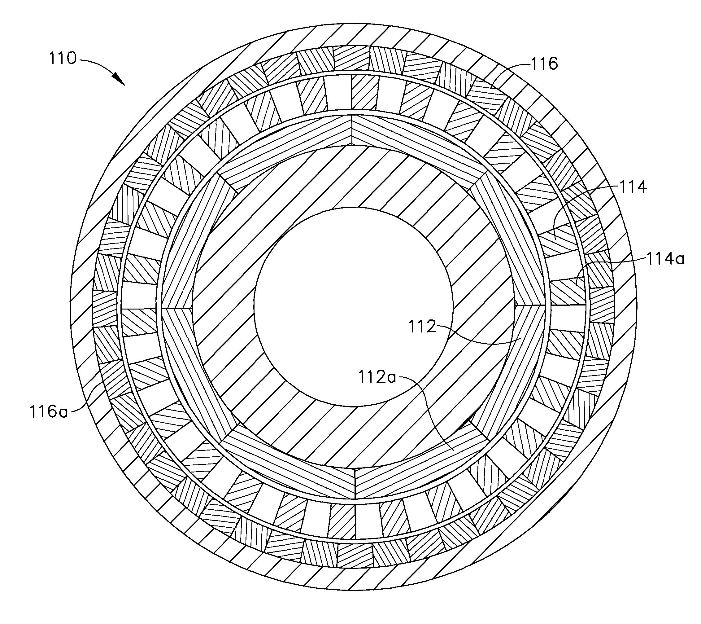
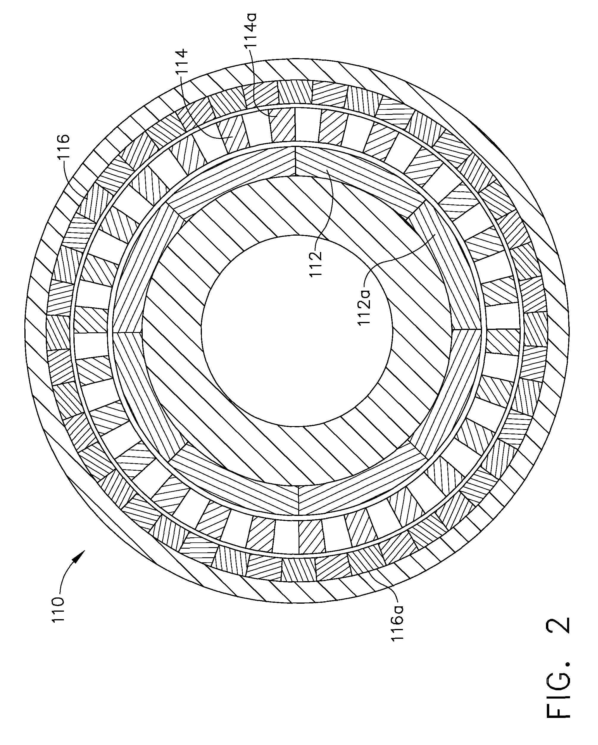
[0037]Referring next to FIG. 2, a magne...


PUM


Abstract

A system for transferring torque between a pair of independently, concurrently rotating shafts of a turbofan engine includes a magnetic gearbox. The magnetic gearbox has a first ring structure, a second ring structure and an intermediate ring structure. Each ring structure has an annular aperture therethrough and a plurality of permanent magnets embedded therein. The intermediate ring structure is disposed between the first and the second ring structures. Each ring structure is coaxially concentric with, and independently rotatable with respect to the remaining ring structures. The first and second ring structures are each coupled to separate ones of the rotating engine shafts, and the intermediate ring is operable to transfer torque between the pair of shafts. Preferably, the intermediate ring structure is coupled to a rotating machine. The rotating machine has a controller, and is operable for adjusting a ratio of torque transferred between the pair of shafts.

Description

FIELD OF THE INVENTION[0001]The present invention is directed to a method and apparatus for coupling of rotating machines, and more specifically to coupling of high pressure (HP) and low pressure (LP) turbine shafts of a turbofan machineBACKGROUND OF THE INVENTION[0002]A gas turbine engine generally includes one or more compressors followed in turn by a combustor and high and low pressure turbines. These engine components are arranged in serial flow communication and disposed about a longitudinal axis centerline of the engine within an annular outer casing. The compressors are driven by the respective turbines and compressor air during operation. The compressor air is mixed with fuel and ignited in the combustor for generating hot combustion gases. The combustion gases flow through the high and low pressure turbines, which extract the energy generated by the hot combustion gases for driving the compressors, and for producing auxiliary output power.[0003]The engine power is transferr...

Claims


Application Information

Patent Timeline
Patent Type & Authority Patents(United States)
IPC IPC(8): H02K7/10
CPCF01D15/10F02C3/113F02C7/32F02C7/36H02K49/102F05D2220/76F05D2220/768F05D2220/327F05D2260/40311F05D2260/404
Inventor KERN, JOHN M.DE BEDOUT, JUAN M.CHUNG, KIYOUNGWASZAK, MICHAL-WOLFGANGSHAH, MANOJ RAMPRASADTOOT, PETER D.QU, RONGHAIWU, WEI
Owner GENERAL ELECTRIC CO
Why Eureka
Try Eureka