Turbocharged internal combustion/steam hybrid engine

a hybrid engine and internal combustion technology, applied in the direction of machines/engines, mechanical equipment, lighting and heating apparatus, etc., can solve the problems of unsatisfactory gas production status and large quantity of unfriendly gases, and achieve the effect of reducing friction, reducing pumping and friction losses, and increasing total efficiency

Inactive Publication Date: 2010-09-14
MCILROY ROBERT
View PDF8 Cites 17 Cited by
  • Summary
  • Abstract
  • Description
  • Claims
  • Application Information

AI Technical Summary

Benefits of technology

[0006]This invention is to recover a large portion of the lost heat and also reduce pumping and friction losses in the heat recovery steam cylinders, the two stroke part of the engine. In this case, from the same fuel being consumed by the two combustion cylinders ...

Problems solved by technology

The reciprocating internal combustion engine has considerable inherent deficiencies which account for the waste of most of the heat produced from the combustion of the hydrocarbon fuel.
This process also produces a large quantity of unfriendly gases that p...

Method used


Image

  • Turbocharged internal combustion/steam hybrid engine
  • Turbocharged internal combustion/steam hybrid engine
  • Turbocharged internal combustion/steam hybrid engine

Examples


Embodiment Construction

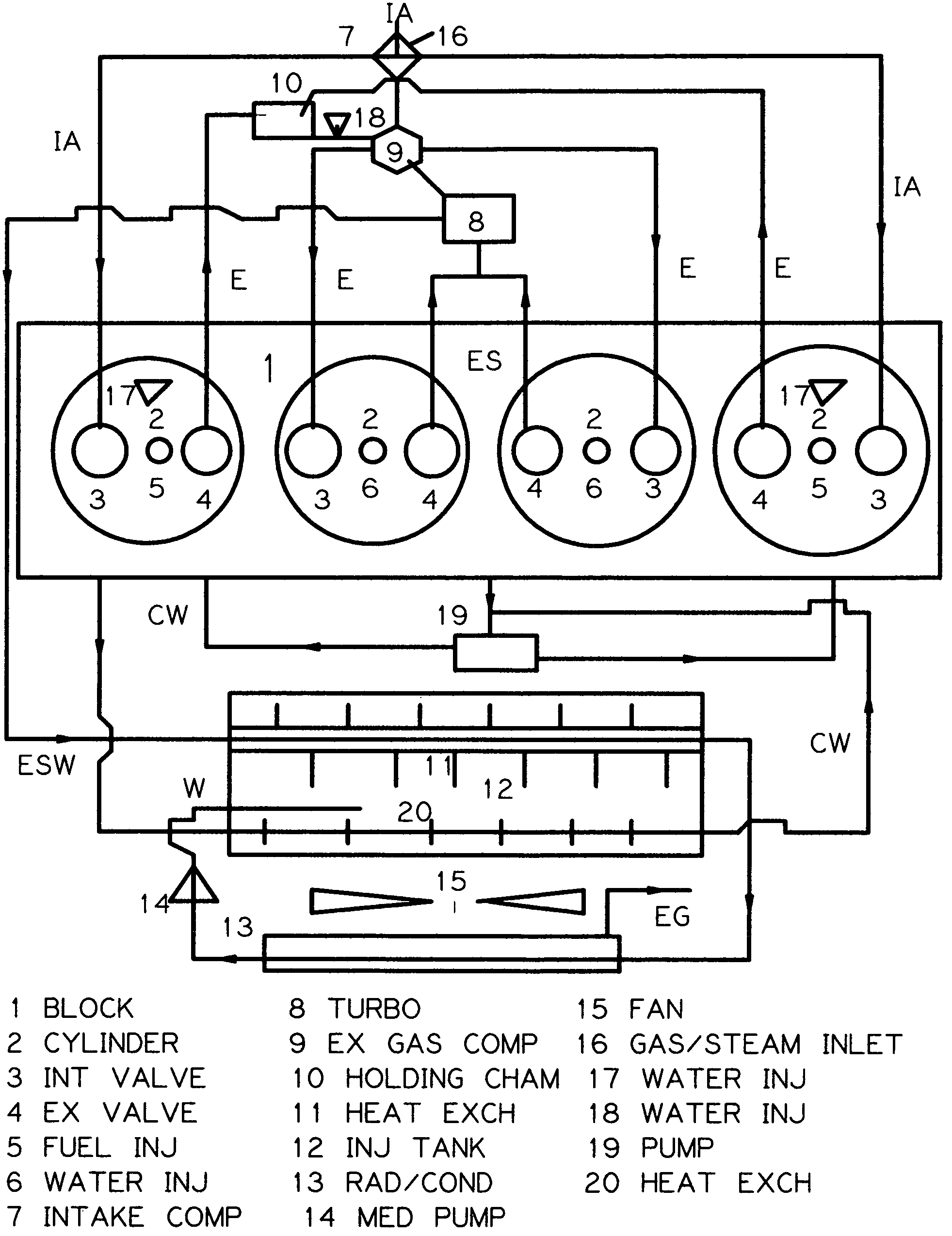
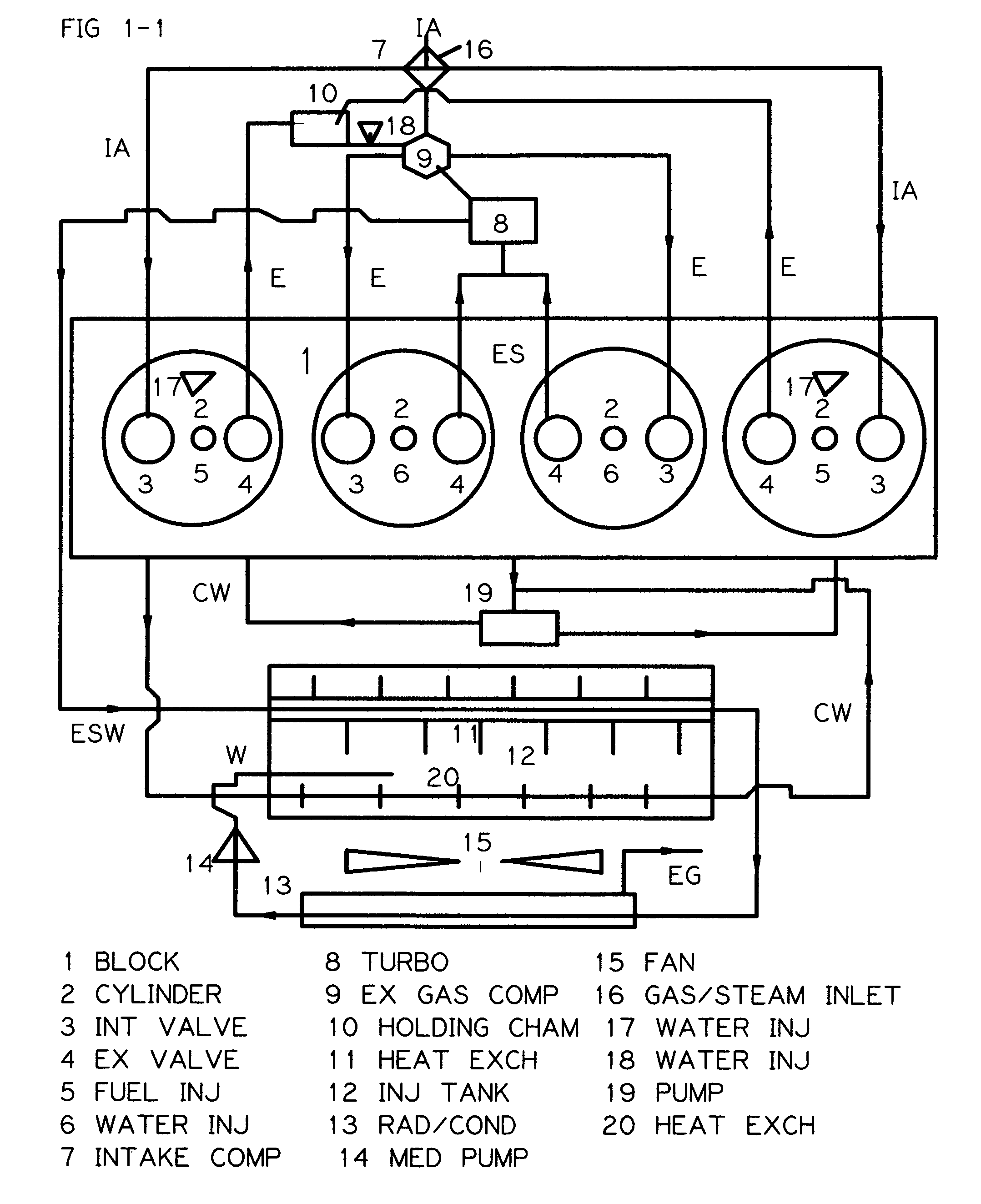
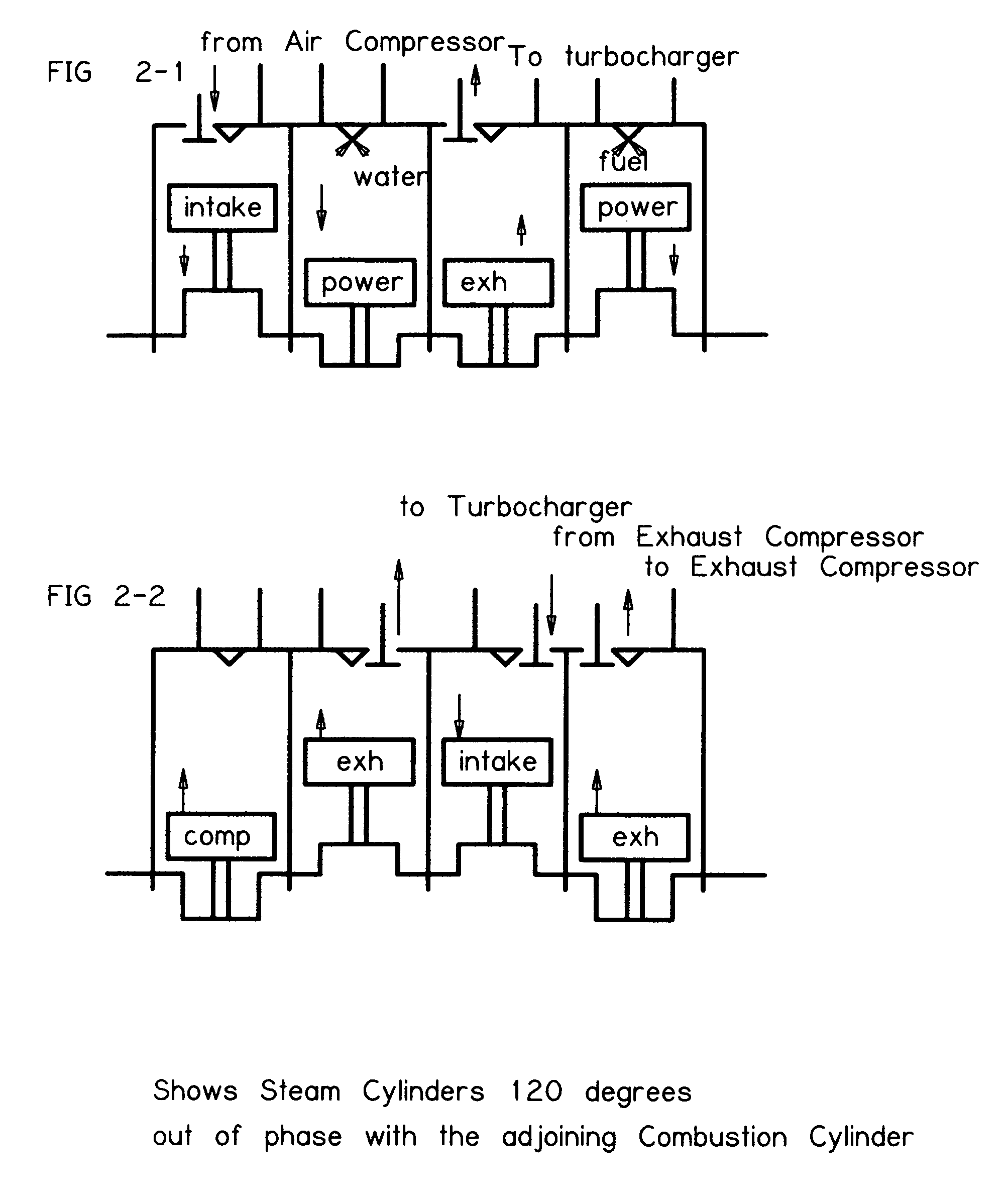
[0015]FIG. 1-1 In the conventional compression ignition four cylinder in line engine block 1 shown, two cylinders would be combustion cylinders and two would be heat recovery steam cylinders. The combustion cylinders 2-5, would be 360 degrees out of phase with each other, and the heat recovery cylinders 2-6, 120 degrees out of phase with each other and 120 degrees out of phase with their adjoining combustion cylinder. This would produce six power strokes for every two revolutions of the engine, and an almost vibration free quiet smooth running engine.

[0016]The camshaft of this engine has been modified so that both cylinders 2-5, operate as four stroke cylinders while the inner two 2-6, as two stroke cylinders with double camshaft lobes for each valve, intake and exhaust. Another modification to the camshaft makes the two center cylinder intake valves 3, to have a low lift and duration of lift.[0017]a) Combustion cylinders 2-5, which operate on an Otto cycle have four strokes, intake...


PUM


Abstract

An engine (FIG. 1-1) comprising of multiple cylinders designated (2-5) combustion cylinders and (2-6) for heat recovery steam cylinders, each cylinder having a piston connected to a common crankshaft. The combustion cylinders operate on a four stroke cycle and the heat recovery steam cylinders operate on a two stroke cycle. The exhaust gas from the combustion cylinders is pressurized by a compressor, driven by a turbine, before entry into the heat recovery steam cylinders. This happens during the intake/power stroke of the heat recovery steam cylinders, as the intake valve closes, after top dead center, heated pressurized water is injected into the cylinder and spontaneously turns to steam driving the receding piston down. This heated exhaust gas and steam is expelled from the heat recovery steam cylinders to drive the turbine which in turn drives two compressors, one to compress the exhaust gas and one to compress the intake air.

Description

BACKGROUND OF THE INVENTION[0001]The invention relates to multi-cylinder reciprocating internal combustion engines.[0002]The reciprocating internal combustion engine has considerable inherent deficiencies which account for the waste of most of the heat produced from the combustion of the hydrocarbon fuel. This process also produces a large quantity of unfriendly gases that pollute the atmosphere. This invention is to make a marked improvement in the utilization of this heat and by absorbing gases and particulate matter make them easier to remove. With a turbocharger coupled to two separate compressors the engine would perform equivalent to or better than a four cylinder engine of similar size. Fuel economy would be immensely improved, and emissions significantly reduced.[0003]Prior art shows that attempts have been made through six stroke engines and exhaust transfer within the cylinders and water injections to increase the efficiency of the engine but for various reasons none have ...

Claims


Application Information

Patent Timeline
IPC IPC(8): F02B35/00
CPCF01K21/045F02M25/0227F02B35/00F02B37/00F02B41/08F02D17/026F02G5/02F02M25/03F22B3/04F01N5/02F02B47/02Y02T10/121Y02T10/146Y02T10/144Y02T10/16Y02T10/166Y02T10/12
Inventor MCILROY, ROBERT
Owner MCILROY ROBERT
Why Eureka
Try Eureka