
Oxynitride phosphor and production process thereof, and light-emitting device using oxynitride phosphor

a technology of oxynitride phosphor and phosphor, which is applied in the direction of luminescent compositions discharge tubes/lamp details, etc., can solve the problems of insufficient luminescence intensity near 500 nm, scarce report of study results, and nitride phosphor and oxynitride phosphor. excellent, excellent color rendering

Active Publication Date: 2010-09-14
NICHIA CORP
View PDF32 Cites 24 Cited by
  • Summary
  • Abstract
  • Description
  • Claims
  • Application Information

AI Technical Summary

Benefits of technology

The oxynitride phosphors exhibit high luminescence efficiency and stability, enabling the production of light-emitting devices with improved brightness and color rendering, capable of emitting light in the blue green to yellow region with enhanced reproducibility and adjustable color tone.

Problems solved by technology

However, a white color light-emitting device equipped with the blue color light-emitting element and the YAG-base phosphor emits white color light formed by the color mixture of blue light nearby 460 nm and yellow green light nearby 565 nm, but luminescence intensity nearby 500 nm is insufficient.
However, a nitride phosphor and an oxynitride phosphor are seldom studied, and a study report is scarcely reported.
However, conventional phosphors have low luminescence brightness and are insufficient for being used for a light-emitting device.
In a light-emitting device using light-emitting elements at a near ultraviolet region as an excitation light source, there is used double step excitation that a blue light-base phosphor is excited by said light-emitting elements and the YAG-base phosphor is excited by said excited light, therefore while light having high efficiency is hardly obtained.
Further, a white color light-emitting device combining a phosphor and a light-emitting element of visible light at a short wavelength side region is not produced yet and the light-emitting device practically used is not commercially available.
Further, the above-mentioned oxynitride phosphors and the like described in the patent literatures 1 and 2 have low luminescence brightness and are insufficient for being used for the light-emitting device.
Further, since the oxynitride glass phosphor is a glass body, it is hardly processed in general.

Method used


Image

  • Oxynitride phosphor and production process thereof, and light-emitting device using oxynitride phosphor
  • Oxynitride phosphor and production process thereof, and light-emitting device using oxynitride phosphor
  • Oxynitride phosphor and production process thereof, and light-emitting device using oxynitride phosphor

Examples


embodiment 1

[0156]Embodiment 1 relates to the oxynitride phosphor which is suitable for being used in combination with a light-emitting element, in particular, a nitride semiconductor element, and the phosphor is a phosphor which is excited by the light of a nitride semiconductor light-emitting element and generates light having a wavelength different from the light from the light-emitting element.

[0157]The oxynitride phosphor related to Embodiment 1 uses a rare earth element, and is a phosphor comprising an oxynitride phosphor crystal containing at least one or more of Group II elements selected from the group consisting of Be, Mg, Ca, Sr, Ba and Zn, and at least one or more of Group IV elements selected from the group consisting of C, Si, Ge, Sn, Ti, Zr and Hf.

[0158]Wherein the oxynitride phosphor crystal is an oxynitride phosphor comprising, for example, crystal which belongs to the rhombic system and is shown in the later-mentioned examples.

[0159]The combination of Group II elements and Gro...

embodiment 2

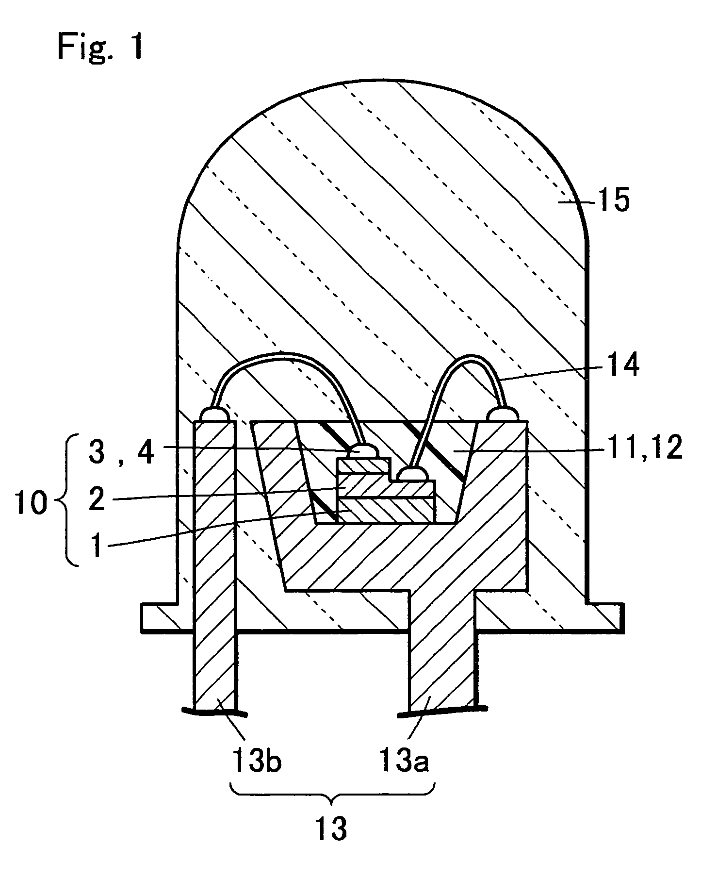
[0209]FIG. 1 is a section view showing the constitution of the light-emitting device of Embodiment 2 related to the present invention, and the present light-emitting device has at least a light-emitting element and the first phosphor converting the wavelength of at least the portion of light from said light-emitting element. Hereat, in particular, the light-emitting device of Embodiment 2 is characterized in using the oxynitride phosphors of Embodiment 1 as the first phosphor.

[0210]Further, in the present specification, the relation between the name of color and the chromaticity coordinate is according to JIS Z8110.

[0211]In the light-emitting device of Embodiment 2, a light-emitting element 10 is composed of a sapphire substrate 1, a semiconductor layer 2 formed on the sapphire substrate 1, and positive and negative electrodes 3, 4 formed on the semiconductor layer 2. The light-emitting element 10 is die-bonded in the cup of the lead frame 13a, and the positive and negative electrod...

embodiment 3

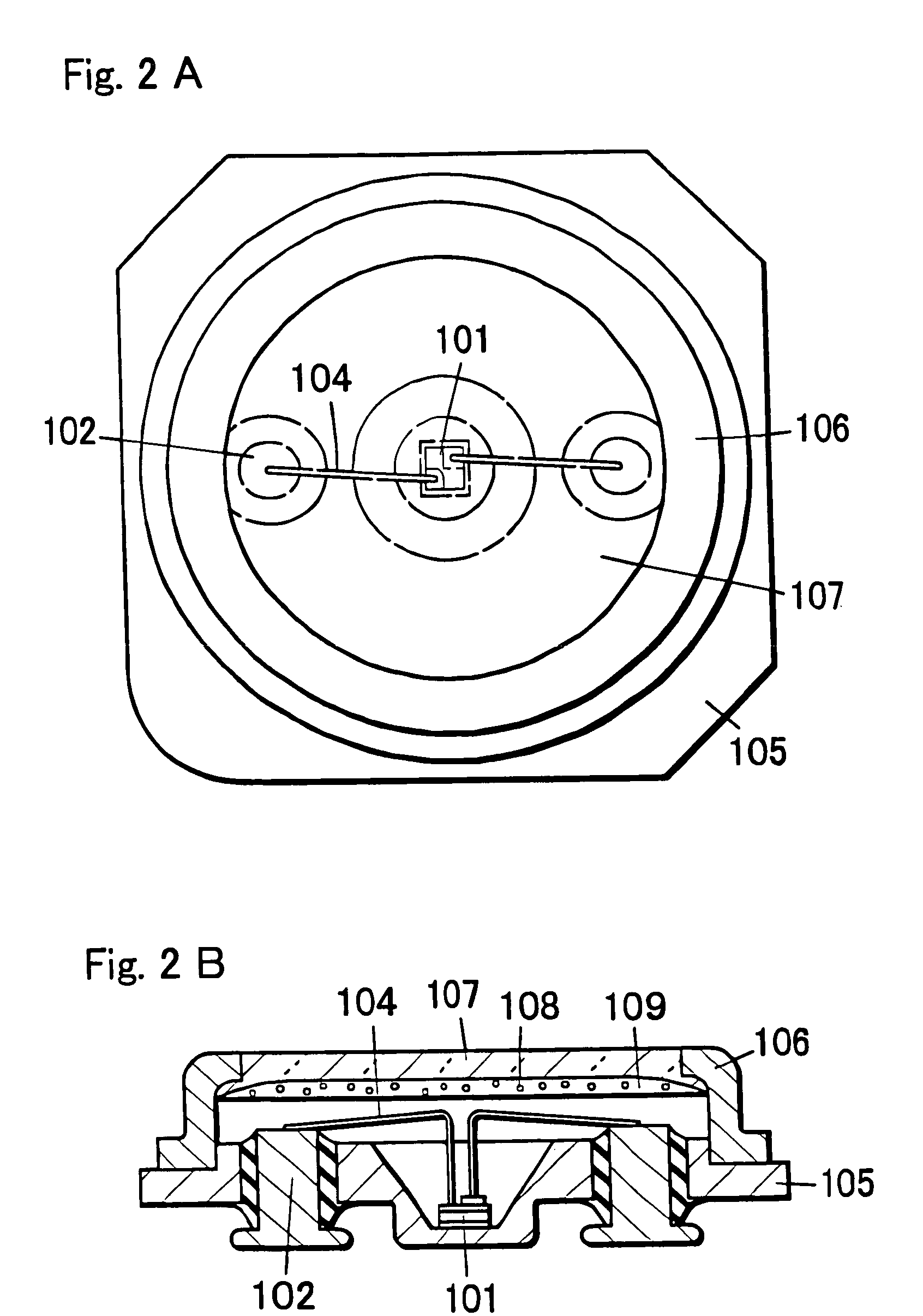
[0254]FIG. 2 is a plane view showing the surface mounting type light-emitting device of Embodiment 3 related to the present invention (FIG. 2A and a section view (FIG. 2B)). The light-emitting device of Embodiment 3 is a surface mounting type light-emitting device. In the light-emitting device of Embodiment 3, a nitride semiconductor light-emitting element which emits light at an ultraviolet region can be used as the light-emitting element 101, and a nitride semiconductor light-emitting element which emits light at a blue region can be also used. Further, the specific constitution is similar as the light-emitting element of Embodiment 2.

[0255]Hereat, the light-emitting element 101 which emits light at an ultraviolet region is illustrated as an example. In Embodiment 3, the light-emitting element 101 is a nitride semiconductor light-emitting element which has an InGaN semiconductor whose luminescence peak wavelength is about 370 nm as a luminescent layer. The more specific LED elemen...


PUM

PropertyMeasurementUnit
luminescence peak wavelengthaaaaaaaaaa
weight %aaaaaaaaaa

Abstract

An oxynitride phosphor consisting of a crystal containing at least one or more of Group II elements selected from the group consisting of Be, Mg, Ca, Sr, Ba and Zn, at least one or more of Group IV elements selected from the group consisting of C, Si, Ge, Sn, Ti, Zr and Hf, and a rare earth element being an activator R, thereby providing a phosphor which is excited by an excitation light source at an ultraviolet to visible light region and which has a blue green to yellow luminescence color that is wavelength converted.

Description

[0001]This application is the U.S. national phase of international application PCT / JP2003 / 013157 filed 15 Oct. 2003 which designated the U.S. and claims benefit of JP 2002-301636; JP 2002-301637; JP 2002-381025; JP 2003-28610; JP 2003-28611; JP 2003-70043, dated Oct. 16, 2002; Oct. 16, 2002; Dec. 27, 2002; Feb. 5, 2003; Feb. 5, 2003; and Mar. 14, 2003, the entire content of which is hereby incorporated by reference.BACKGROUND OF THE INVENTION[0002]1. Field of the Invention[0003]The present invention relates to a phosphor which emit a light by being excited by light, electromagnetic waves such as X-rays, electron beam, and specifically, relates to a light-emitting device for usual illuminations such as a fluorescent lamp, illuminations mounted on a car, back lights for liquid crystal, displays and the like. Specifically, the present invention relates to a white color and multi-color light-emitting device using a semiconductor light-emitting element.[0004]2. Description of the Related...

Claims


Application Information

Patent Timeline
Patent Type & Authority Patents(United States)
IPC IPC(8): C09K11/59C09K11/66C09K11/64C01B21/082C09K11/62C09K11/63C09K11/08H01L33/00C09K11/77H01L33/50
CPCC09K11/0883C09K11/7734H01L33/502H01L2224/48091H01L2224/45144H01L2224/73265H01L2224/49107H01L2224/48247H01L2224/48464H01L2924/00014H01L2924/00H01L2924/12032H01L2224/45139H01L2924/181H01L2224/48257H01L2224/45124H01L2224/45147H01L2224/45169C09K11/77347H01L2924/00012H01L2224/45015H01L2924/207C09K11/66C09K11/59
Inventor TAMAKI, HIROTOTAKASHIMA, SUGURUKAMESHIMA, MASATOSHINAITOU, TAKAHIRO
Owner NICHIA CORP
Learn More