Sensor-based gamma correction of a digital camera

a digital camera and sensor technology, applied in the field of imaging systems, can solve the problems of image content loss, dim lighting, and saturating bright areas of images, and achieve the effect of widening the effective dynamic range, reducing the gain, and reducing the loss of details

Inactive Publication Date: 2010-09-14
FLIR SYST INC
View PDF8 Cites 39 Cited by
  • Summary
  • Abstract
  • Description
  • Claims
  • Application Information

AI Technical Summary

Benefits of technology

[0011]In accordance with the present invention, a customizable and user-definable voltage-time curve (i.e., a time-varying voltage) is applied to the antibloom structure of an image sensor. The voltage-time curve defines a number of charge integration periods during each of which a different a voltage is applied to the antibloom structures. Charges generated in response to a low level light are fully captured, whereas charges generated in response to a relatively higher level light spill over in a controlled manner. The resulting pixel response to varying levels of light is equivalent to a gamma-corrected behavior. Accordingly, the image sensor's response results in higher gains at low light levels and progressively lower gains at the higher light levels. Therefore, a wider effective dynamic range is attained.

Problems solved by technology

This is both advantageous and disadvantageous.
If the gain of the sensor is reduced to avoid saturation in the high brightness area, details can be lost in the dimly lit areas.
Conversely, if the gain is increased to capture the details in the dimly lit areas, the bright areas of the image will saturate, and image content is lost.
Because shot noise at higher illumination makes very fine gray-scale resolution less usable, this method compresses bright light levels and sacrifices information.
While this method is useful for shifting between bright scenes and dim scenes, it cannot effectively handle a scene with both bright and dim areas simultaneously.
Further, because this method requires adjustments on a pixel-to-pixel basis, objectionable artifacts may arise due to pixel-to-pixel non-linearity.
This method takes longer to capture an image, and the procedure to effectively combine the two images is difficult and error-prone.

Method used


Image

  • Sensor-based gamma correction of a digital camera
  • Sensor-based gamma correction of a digital camera
  • Sensor-based gamma correction of a digital camera

Examples


Embodiment Construction

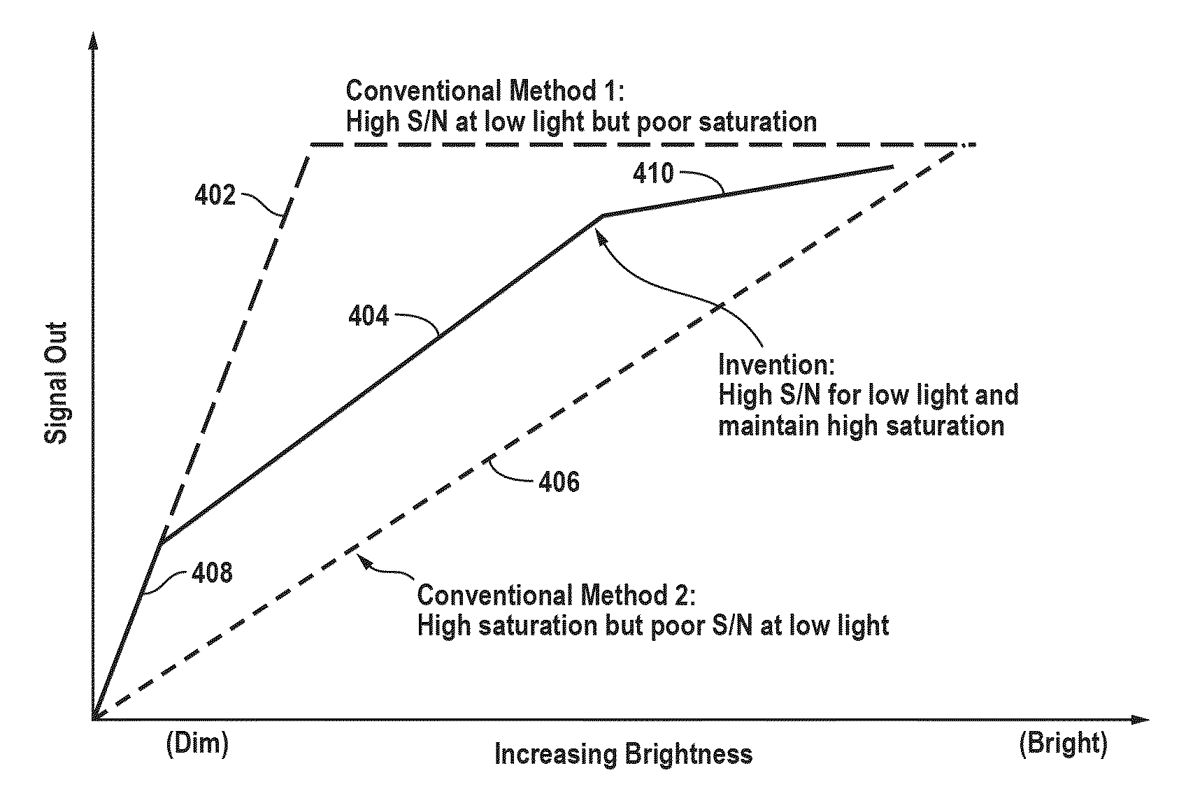
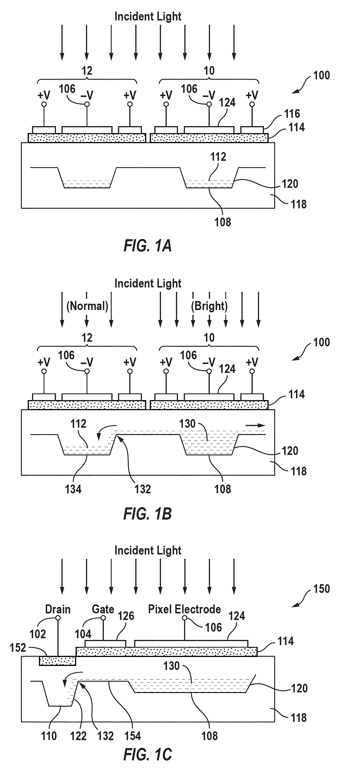
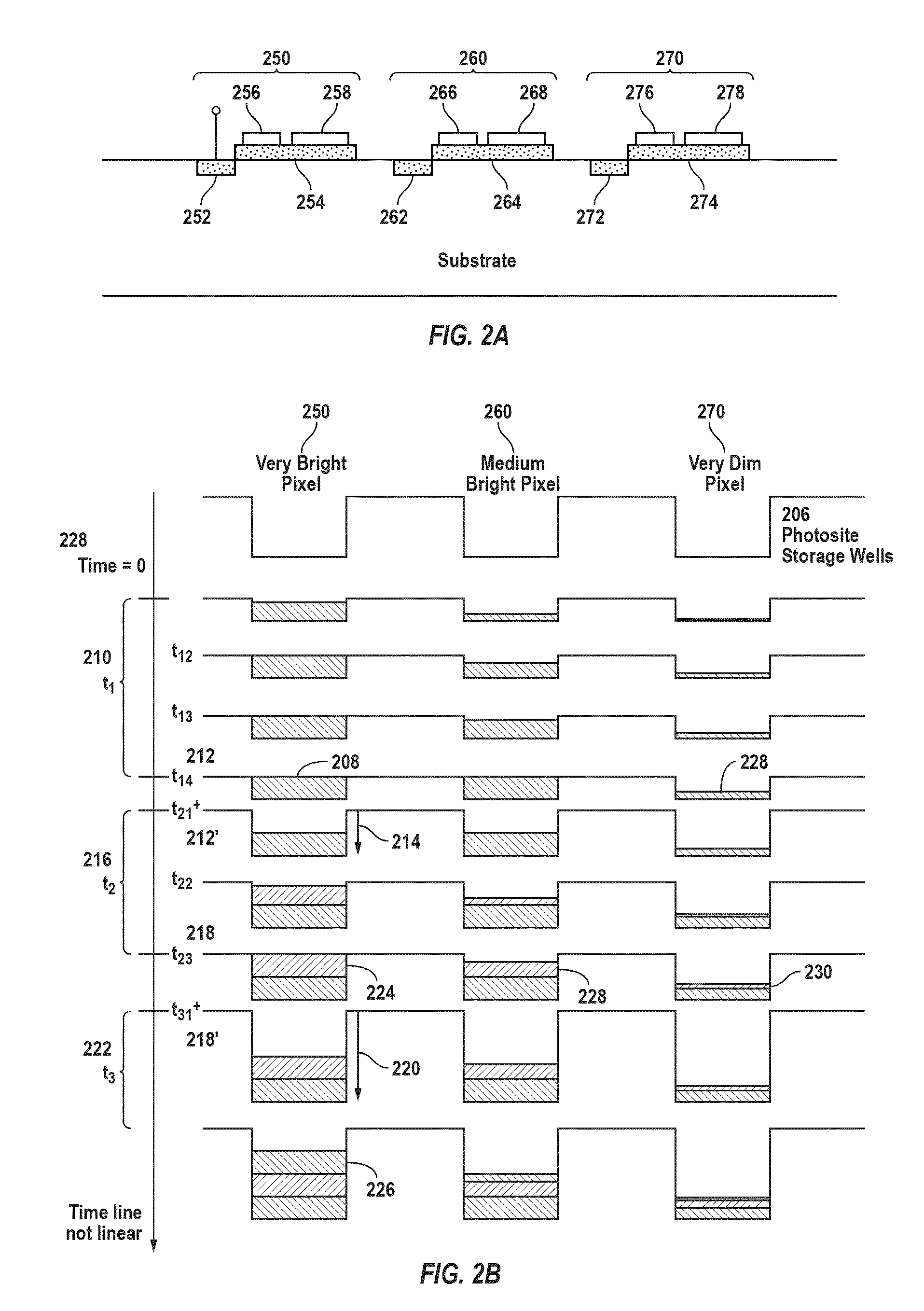
[0019]In accordance with one embodiment of the present invention, a customizable and user-definable voltage-time curve is applied to the antibloom structure of an image sensor, and the resulting pixel response to varying levels of brightness is equivalent to gamma-corrected behavior. More specifically, the invention takes advantage of the ability of an image sensor having an anti-blooming drain and specialized timing circuitry to skim off excess charge at a pixel once the level has exceeded a definable threshold. In particular, by varying the voltage on the antibloom drain during light integration, pixel charges generated in response to a low level light are fully captured, whereas pixel charges generated in response to a bright light spill over in a controlled manner. Therefore, a wider effective dynamic range is attained.

[0020]The following description is provided with reference to an imaging system with a charge coupled device (CCD) based image sensor. It is understood, however, ...


PUM

PropertyMeasurementUnit
time-varying voltageaaaaaaaaaa
voltageaaaaaaaaaa
timeaaaaaaaaaa

Abstract

The anti-blooming structure of an image sensor is supplied with varying voltages during different integration periods such that charges generated in response to low level light are fully captured, whereas charges generated in response to a bright light spill over in a controlled manner. Accordingly, sensor's response may be generated to result in higher gains at low light levels and progressively lower gains at the higher light levels.

Description

BACKGROUND OF THE INVENTION[0001]The present invention relates generally to imaging systems utilizing imaging sensors and more particularly to imaging systems with capability of periodically re-setting photosites and requiring a wide dynamic range within the same scene. Field of applications may cover a broad range of areas including but not limited to inspection and testing where imaging is used, digital x-ray systems, surveillance imaging applications, film scanning, night vision and automotive applications.[0002]Typical scenes viewed by a camera may have a wide range of illumination conditions across the image. That is, the scene may have details in dimly lit areas that need to be resolved while simultaneously needing to resolve very bright areas of the scene without saturating the image sensor and camera system. Conventional film-based cameras are able to resolve the detail in both the dimly lit areas of a scene and brightly lit areas of the scene simultaneously because of the n...

Claims


Application Information

Patent Timeline
Patent Type & Authority Patents(United States)
IPC IPC(8): H04N5/202H04N5/335H01L27/00B21F9/00H04N5/20
CPCH04N5/35509H04N5/3592H04N5/372H04N25/571H04N25/622H04N25/71
Inventor GARDNER, DAVID W.
Owner FLIR SYST INC
Why Eureka
Try Eureka