Radial impaction bone tamp and associated method

a radial impaction and bone graft technology, applied in the field of orthopaedics, can solve the problems of stress on joints or damage to joints in the body, wear and tear of cartilage, and damage to bones, cartilage or other connective tissue such as tendons or ligaments, and achieve greater radial impaction force, improve the compaction of bone graft material, and improve the effect of radial impacting for

Active Publication Date: 2010-09-21
DEPUY ORTHOPAEDICS INC +1
View PDF71 Cites 14 Cited by
  • Summary
  • Abstract
  • Description
  • Claims
  • Application Information

AI Technical Summary

Benefits of technology

[0023]The technical advantage of the present invention further include the ability to provide for a greater radial impacting force. This greater impaction force may provide improved compaction of the bone graft material. For example, according an aspect of the present invention, an instrument is provided with a first component moveable radially with respect to a second component with the component which is moveable radially with respect to the longitudinal movement of the second component importing radial impaction force on the bone graft material. Thus, the present invention provides for greater radial impaction force and improved impaction of the bone graft material.
[0024]Yet another technical advantage of the present invention includes the ability to provide a cavity for receiving an implant formed of bone graft material which provides a shape that matches the implant. For example, according an aspect of the present invention, the outer periphery of a first component which is moveable radially with respect to a second component, may have a outer contour with a shape to conform with the prosthesis such that, as the instrument is used, the outer periphery of the instrument forms a cavity formed of the bone graft material which matches the shape of the implant. Thus, the present invention provides for a shape of a cavity that matches the shape of the implant. Such matching of the shape of the cavity of bone graft material to the implant provides for improved stability of the implant in the long bone.
[0025]Yet another technical advantage of the present invention is the ability of the instrument of the present invention to replace a set of tamps with one instrument or tamp of the present invention. The ability to replace a set of tamps with a solitary instrument of the present invention will result in reduced inventory and reduced inventory cost and manufacturing cost for manufacturing a large quantity of sets of tamps.
[0026]Prior art systems utilize a series of progressively larger tamps to form the cavity within the bone graft material. By providing the tamp of the present invention, a solitary tamp which expands readily outward will replace this series of tamps. For example, according to one aspect of the present invention, an instrument is provided with a first component moveable radially with respect to a second component to urge the bone material against the cortical wall of the bone. The radial motion of the first tamp provides for a tamp which can replace the set of progressively larger diameter tamps that would otherwise be required. Thus, the present invention provides for a solitary instrument to replace a set of multiple tamps.
[0027]Another advantage of the present invention includes the ability to reduce the time of performing an arthroplasty. For example, according to one aspect of the present invention, an instrument is provided with a first component moveable radially with respect to a second component to urge the bone material against the cortical wall of the bone. The instrument of the present invention is struck on the end of the instrument and the final form of the cavity for the implant is formed in one insertion of one instrument and one tamping of the instrument. In prior arts systems a multitude of progressively larger tamps must be separately inserted and removed from the cavity and separately struck to compact the bone graft material. Thus, the present invention provides for a reduction in the time to perform an arthroplasty.

Problems solved by technology

The joints in the body are stressed or can be damaged in a variety of ways.
Over time, the normal use of a joint may wear down the cartilage and bring the moving bones in a direct contact with each other.
In contrast, in normal use, a trauma to a joint, such as the delivery of a large force, from an accident, for example, an automobile accident, may cause considerable damage to the bones, the cartilage or to other connective tissue such as tendons or ligaments.
Unfortunately, some patients who have undergone partial or total joint replacements require revision surgery.
For one, fixation of the joint may be compromised.
A trauma of to the joint may result in the loosening or the loosening of the joint may have been caused by other factors, such as an insufficient bond between the implant and the host bone.
The loosening of an implant can be quite painful and also can pose danger to the patient.
For example, movement of the loose implant within the bone may fracture the bone itself.
For example, particle debris from the cartilage substitute member or even from any of the other implants may cause osteolysis in the patient.
In general osteolysis is the body's natural immune response to foreign objects which result in inflammation and pain in the joint.
Another reason why revision surgery may be necessary, is due to death of part of the bone.
A bone requires stress in order to remain strong and any bone that is not stressed will become weak and fragile.
Revision surgery is more complicated than the primary partial or total joint replacements since it requires removal of the previously inserted stem implant and introduction of another stem implant.
This method is wrought with several problems.
One of these problems is that in order to tamp the morselized bone into the cavity, the distal portion of the cavity must first be filled and a large quantity of graft material must be used.
It may be traumatic for the patient as additional morselized bone must be harvested from the patient.
Conversely, when bone substitute material issues, a larger and more expensive amount of material must be used.
Further the packing of the entire canal may cause additional blood loss and blood flow as the blood is absorbed and moved toward the open portion of the cavity as the material continues to be packed by the tamps.
Further, the use of the tamps create a limit on the shape of the cavity created by the tamp as well as limiting the precision of the fit of the tamp to the prosthesis stem.

Method used


Image

  • Radial impaction bone tamp and associated method
  • Radial impaction bone tamp and associated method
  • Radial impaction bone tamp and associated method

Examples


Embodiment Construction

[0067]Embodiments of the present invention and the advantages thereof are best understood by referring to the following descriptions and drawings, wherein like numerals are used for like and corresponding parts of the drawings.

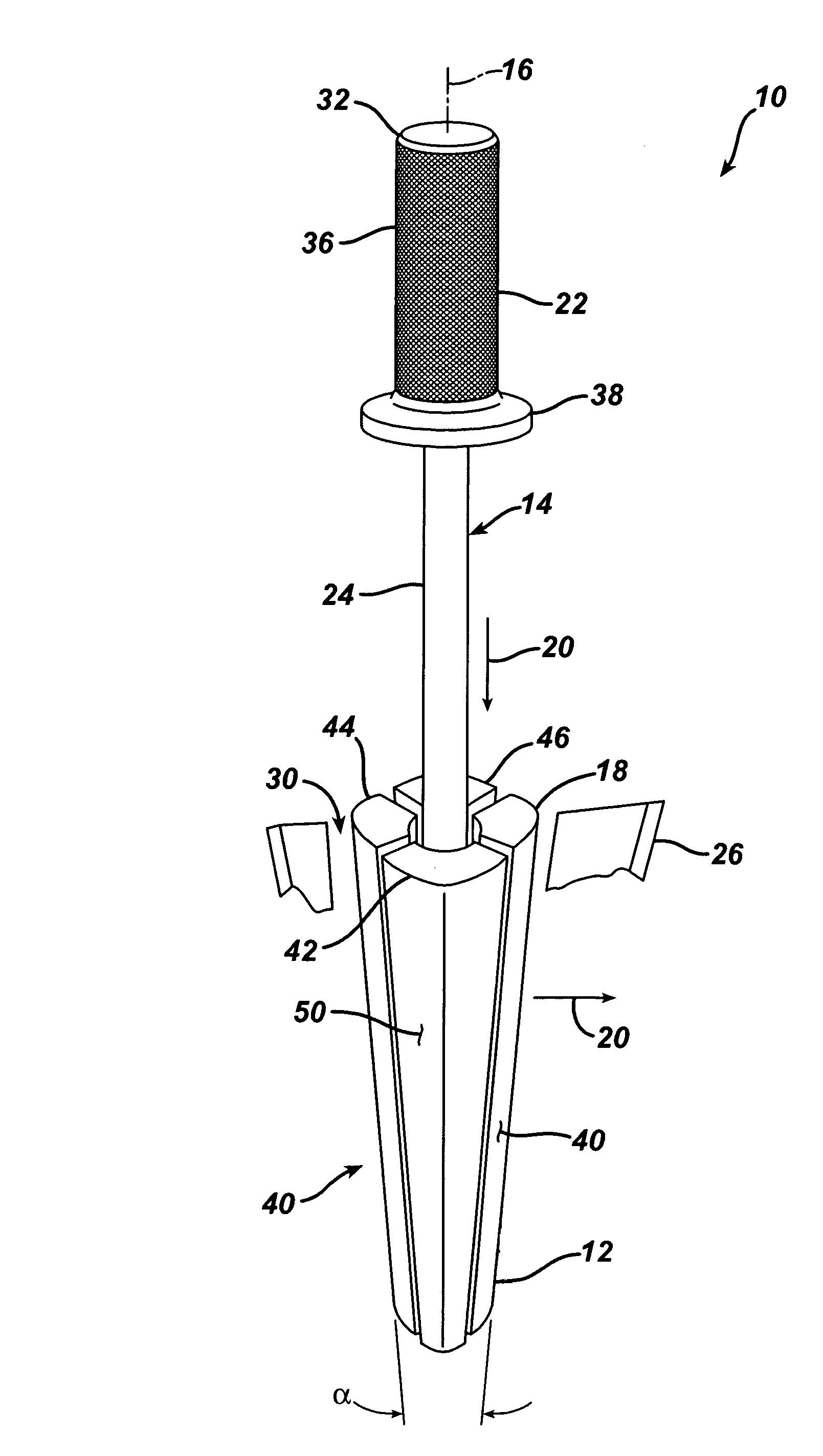
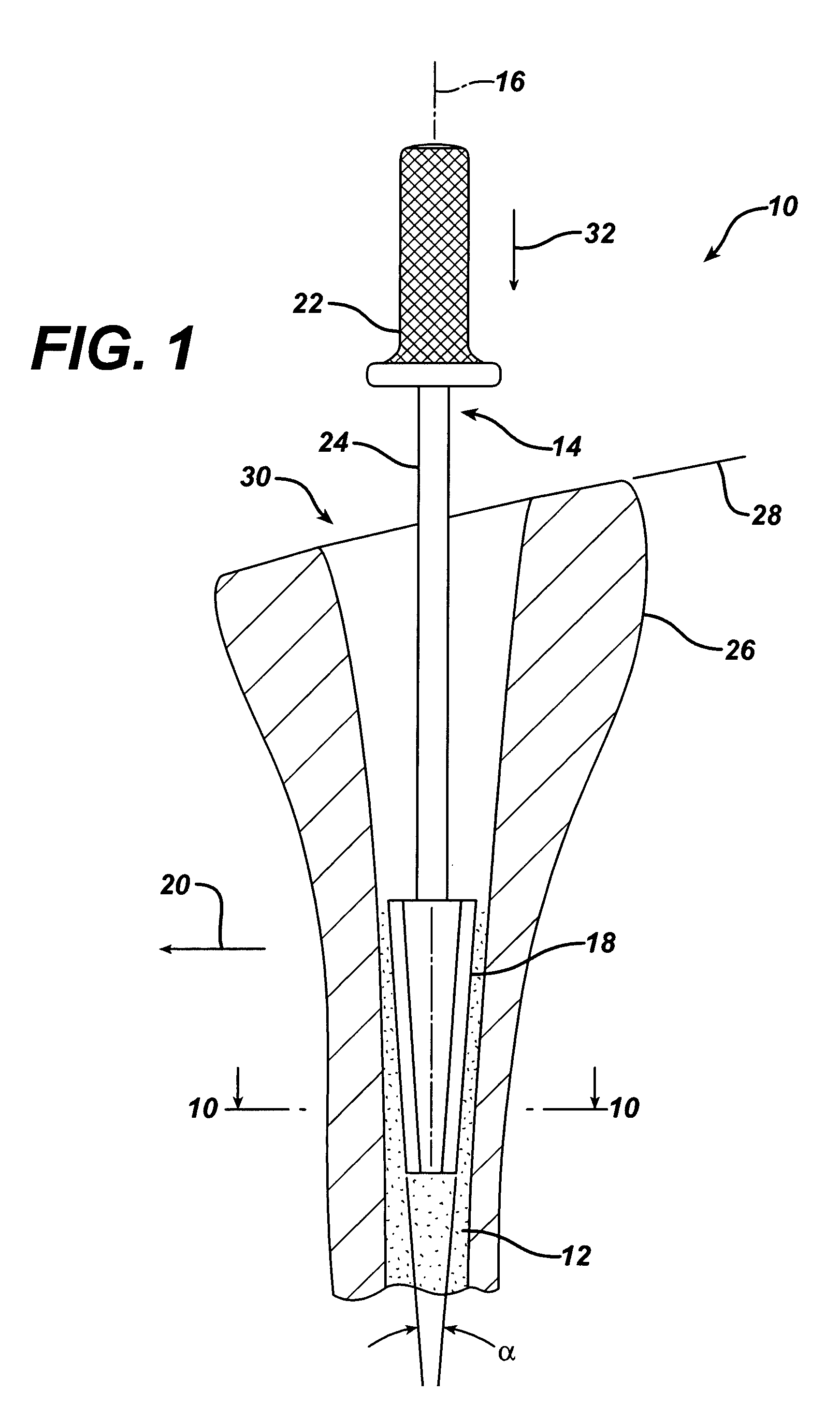
[0068]According to the present invention and referring now to FIG. 1, an instrument 10 for compacting bone material 12 is shown. The instrument 10 includes a first component 14 defining a longitudinal axis 16 of the first component 14. The instrument 10 also includes a second component 18 which is moveably associated with the first component 14. The second component 18 is moveable at least partially in a radial direction 20 outwardly from the longitudinal axis 16 of the first component 14.

[0069]The first component 14 may, for example, include a body 22 and a stem 24 extending from the body 22. The second component 18 may, for example, be slidably mounted to the stem 24.

[0070]The instrument 10 may be configured, for example, such that the first component 14 or ...


PUM


Abstract

An instrument for compacting bone material is provided. The instrument includes a first component defining a longitudinal axis of the first component and a second component. The second component is moveably associated with the first component. The second component is moveable at least partially in a radial direction outwardly from the longitudinal axis of the first component.

Description

TECHNICAL FIELD OF THE INVENTION[0001]The present invention relates generally to the field of orthopaedics, and more particularly, to an instrument for use in arthroplasty.BACKGROUND OF THE INVENTION[0002]A joint within the human body forms a juncture between two or more bones or other skeletal parts. The ankle, hip, knee, shoulder, elbow and wrist are just a few examples of the multitude of joints found within the body. As should be apparent from the above list of examples of joints, many of the joints permit relative motion between the bones. For example, the motion of sliding, gliding, hinge or ball and socket movements may be had by a joint. For example, the ankle permits a hinge movement, the knee allows for a combination of gliding and hinge movements and the shoulder and hip permit movement through a ball and socket arrangement.[0003]The joints in the body are stressed or can be damaged in a variety of ways. For example, the gradual wear and tear is imposed on the joints thro...

Claims


Application Information

Patent Timeline
Patent Type & Authority Patents(United States)
IPC IPC(8): A61B17/56A61B17/00A61B17/88A61F2/36A61F2/46
CPCA61B17/8858A61F2/4601A61B2017/0046A61F2/36A61F2002/4602A61F2002/4623A61F2/4603
Inventor JONES, MICHAEL C.
Owner DEPUY ORTHOPAEDICS INC
Why Eureka
Try Eureka