Method for effective placement of on-chip decoupling capacitors determined by maximum effective radii

a decoupling capacitor and effective placement technology, applied in the field of effective placement of decoupling capacitors on the chip, can solve the problems of high complexity environment, ineffective decoupling capacitors, high cost, etc., and achieve the effect of reducing and distributing localized current demands

Inactive Publication Date: 2010-09-21
TASIT
View PDF6 Cites 19 Cited by
  • Summary
  • Abstract
  • Description
  • Claims
  • Application Information

AI Technical Summary

Benefits of technology

[0021]To be effective, an on-chip decoupling capacitor should be placed such that both the power supply and the current load are located inside the appropriate effective radius. If this allocation is not feasible, the current load should be partitioned into several circuit blocks, reducing and distributing the localized current demands. The on-chip decoupling capacitors should be allocated to each block while satisfying both effective radii criteria. Summarizing, on-chip decoupling capacitors should be allocated within appropriate effective radii across an IC to satisfy local transient current demands.

Problems solved by technology

Distributing robust and reliable power and ground voltages in such a high speed, high complexity environment is, therefore, a highly challenging task.
During discharge, the current flowing from the decoupling capacitor to the current load results in resistive noise (IR drops) and inductive noise
Beyond this effective distance, the decoupling capacitor is ineffective.
Simplified criteria are developed, however, which significantly overestimate the required decoupling capacitance.
Larger decoupling capacitors have a greater form factor (physical dimension), resulting in higher parasitic impedances.
This methodology results in overestimating the capacitance budget due to the use of a simplified criterion for sizing the on-chip decoupling capacitors.
Also, since the package level power distribution system is modeled as a single lumped resistance and inductance, the overall power supply noise is greatly underestimated.
The proposed algorithm is limited to on-chip decoupling capacitors placed in rows of standard cells (in one dimension).
The technique does not consider the degradation in effectiveness of an on-chip decoupling capacitor located at some distance from the current load.
Otherwise, the charge on the decoupling capacitor will be gradually depleted, making the capacitor ineffective.
The methodology described in the above-referenced Zhao et al. publication therefore results in underestimating the power supply noise and overestimating the required on-chip decoupling capacitance.

Method used


Image

  • Method for effective placement of on-chip decoupling capacitors determined by maximum effective radii
  • Method for effective placement of on-chip decoupling capacitors determined by maximum effective radii
  • Method for effective placement of on-chip decoupling capacitors determined by maximum effective radii

Examples


Embodiment Construction

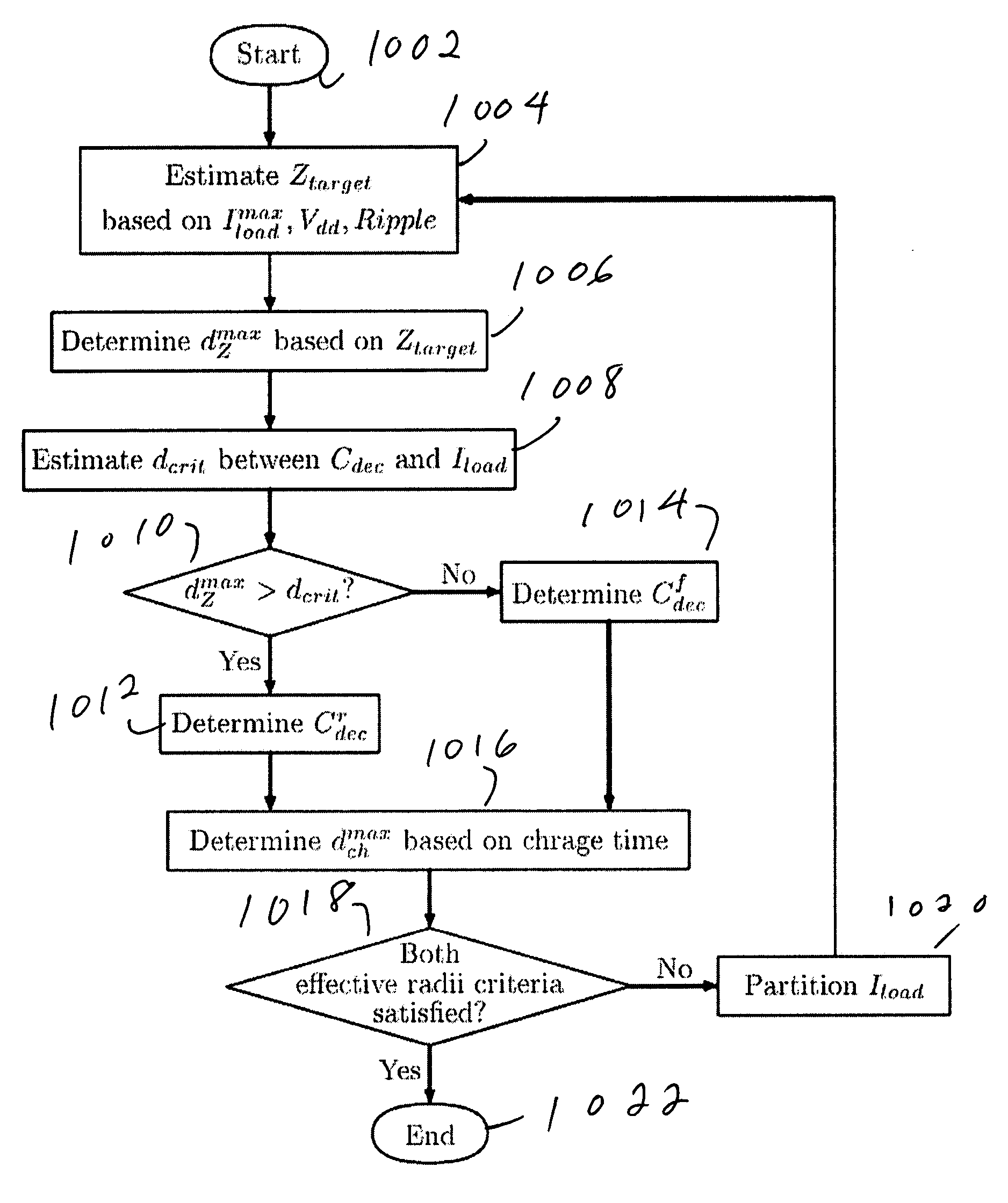
[0038]A preferred embodiment of the invention will be set forth in detail with reference to the drawings, in which like reference numerals refer to like elements or steps throughout.

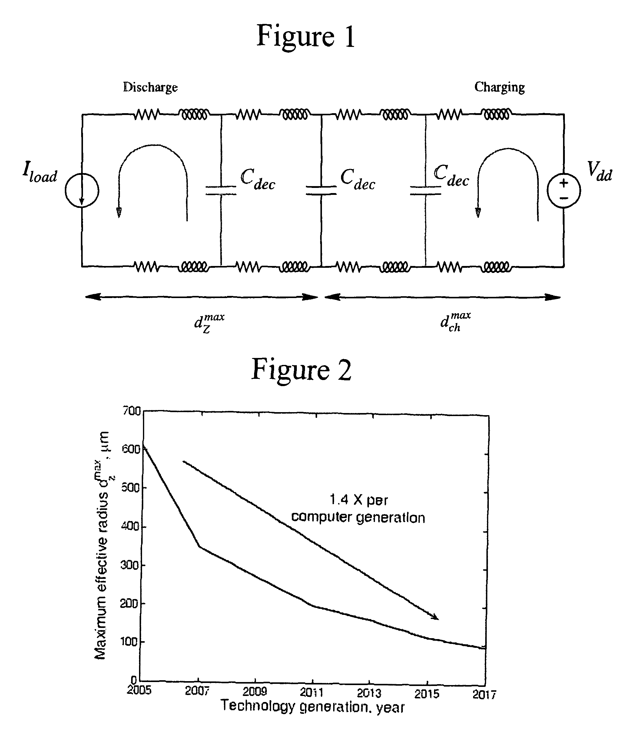
[0039]Neglecting the parasitic capacitance, the impedance of a unit length wire is Z′(ω)=r+jωl, where r and / are the resistance and inductance per length, respectively, and ω is an equivalent frequency, as determined by the rise time of the current load. The inductance l is the effective inductance per unit length of the power distribution grid, incorporating both the partial self-inductance and mutual coupling among the lines. The target impedance of the metal line of a particular length is therefore

Z(ω)=Z′(ω)×d,  (1)

where Z′(ω) is the impedance of a unit length metal line, and d is the distance between the decoupling capacitor and the current load. Substituting the expression for the target impedance Ztarget presented in M. Popovich and E. G. Friedman, “Decoupling Capacitors for Multi-Voltage Power Dist...


PUM


Abstract

The maximum effective radii of an on-chip decoupling capacitor based on a target impedance (discharge) and charge time are determined. To be effective, an on-chip decoupling capacitor should be placed such that both the power supply and the current load are located inside the appropriate effective radius. If this allocation is not feasible, the current load is partitioned into several circuit blocks, reducing and distributing the localized current demands. The on-chip decoupling capacitors are allocated to each block while satisfying both effective radii criteria.

Description

FIELD OF THE INVENTION[0001]The present invention relates to a method for the placement of decoupling capacitors on a chip and more particularly to such a method which uses a maximum effective radii.DESCRIPTION OF RELATED ART[0002]The feature size of integrated circuits (IC) has been aggressively reduced in the pursuit of improved speed, power, and cost. Semiconductor technologies with a feature size of several tens of nanometers are currently in development. The scaling of CMOS is expected to continue for at least another decade. Future nanometer circuits will soon contain more than a billion transistors and operate at clock speeds well over 10 GHz. Distributing robust and reliable power and ground voltages in such a high speed, high complexity environment is, therefore, a highly challenging task.[0003]Decoupling capacitors are widely used to manage power supply noise. A decoupling capacitor acts as a reservoir of charge, which is released when the power supply voltage at a particu...

Claims


Application Information

Patent Timeline
Patent Type & Authority Patents(United States)
IPC IPC(8): G06F17/50G06F9/45
CPCG06F17/5036G06F2217/78G06F30/367G06F2119/06
Inventor POPOVICH, MIKHAILFRIEDMAN, EBY G.
Owner TASIT
Why Eureka
Try Eureka