Method and structure for cooling an electric motor

a technology of electric motors and cooling methods, applied in the direction of cooling/ventilation arrangements, electrical appliances, dynamo-electric machines, etc., can solve the problems of failure to function, extreme heat build-up, catastrophic failure, etc., and achieve the effect of prolonging the life of the motor and extending the life of the brush

Inactive Publication Date: 2010-09-28
SMARTPOOL
View PDF19 Cites 15 Cited by
  • Summary
  • Abstract
  • Description
  • Claims
  • Application Information

AI Technical Summary

Benefits of technology

[0014]It is an additional object of this invention to provide such a method and structure for cooling a small high powered electrical motor which dislodges graphite particles from the contact area between the brushes and commutator extends the life of the brushes.
[0015]It is an additional object of this invention to provide a method and structure for cooling a small high powered electrical motor which extends the life of the motor by extending the life of the brushes.
[0017]Additionally, the air flow is of sufficient strength and pressure to dislodge particulates. Particularly, the brushes of such motors are made of graphite. Small bits of graphite defining dust particles cause build up on the contact area. By providing such a flow of air that dislodges particulates, including graphite dust from the contact area, particulate build up at the contact area is discouraged, if not eliminated. Additionally, it will be appreciated that a commutator having a dirty contact area will lower the motor efficiency. Further, such a dirty contact area will likely generate extra heat due to a partial shorting of the circuit between the commutator and the brushes.
[0026]It is an advantage of this invention to provide such a electrical motor which increases motor life in a confined environment.

Problems solved by technology

As will be readily understood the physical limitations of such spaces and the high speed of the motors means that heat build up can be extreme, especially when such motors are put to constant and heavy usage.
The two weakest points to such small high speed electric motors in a confined space are heat which catastrophically damages the copper windings of the motors and dust or particulate matter build up on the commutator, especially at the contact area between the brushes and the commutator which likewise causes catastrophic failure.
Heat causes the copper wiring of the armature to become so hot it fails to function and then fails catastrophically so that the motor is permanently damaged and needs to be replaced.
Thus, heat is the primary enemy of such motors and there is a long felt need to cool such motors.
As the brushes contact the commutator, wear occurs and very fine graphite particles, dust, in fact, escape into the air and also build up on the commutator at the contact area between the commutator and the brushes.
When enough such particulates build up on the commutator, the brushes will fail to complete the electromagnetic circuit and the motor will no longer operate.
In practice, it has been found that typically first, the copper wire fails cutting motor life as the result of excess heat.
And, subsequently, should the user be able to get by copper wire failure, dust or particulate build up, especially from graphite dust, similarly causes catastrophic and permanent failure.
However, whether integrated or separated from the motor, an axial fan provides high air flow but low air pressure.

Method used


Image

  • Method and structure for cooling an electric motor
  • Method and structure for cooling an electric motor
  • Method and structure for cooling an electric motor

Examples


Embodiment Construction

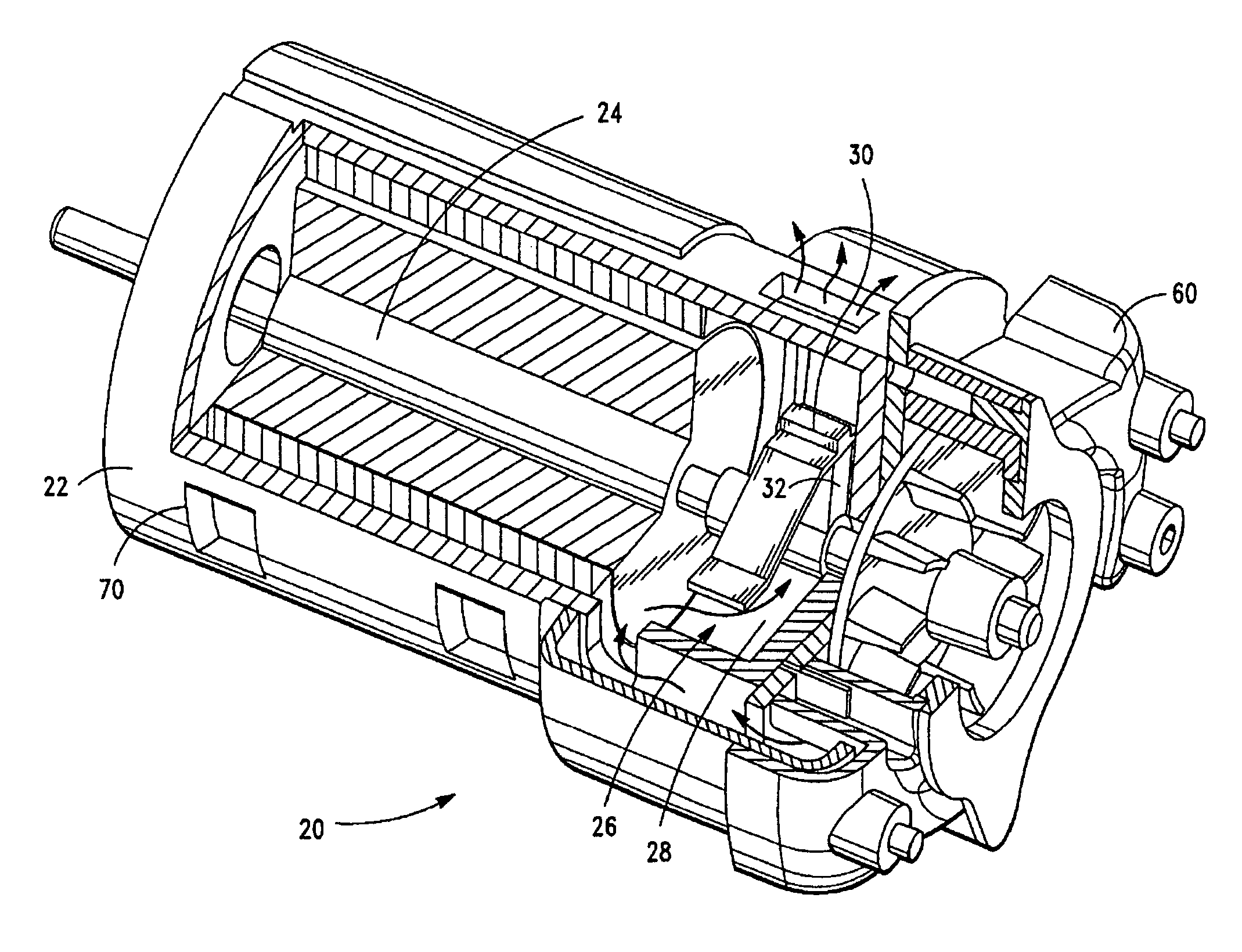
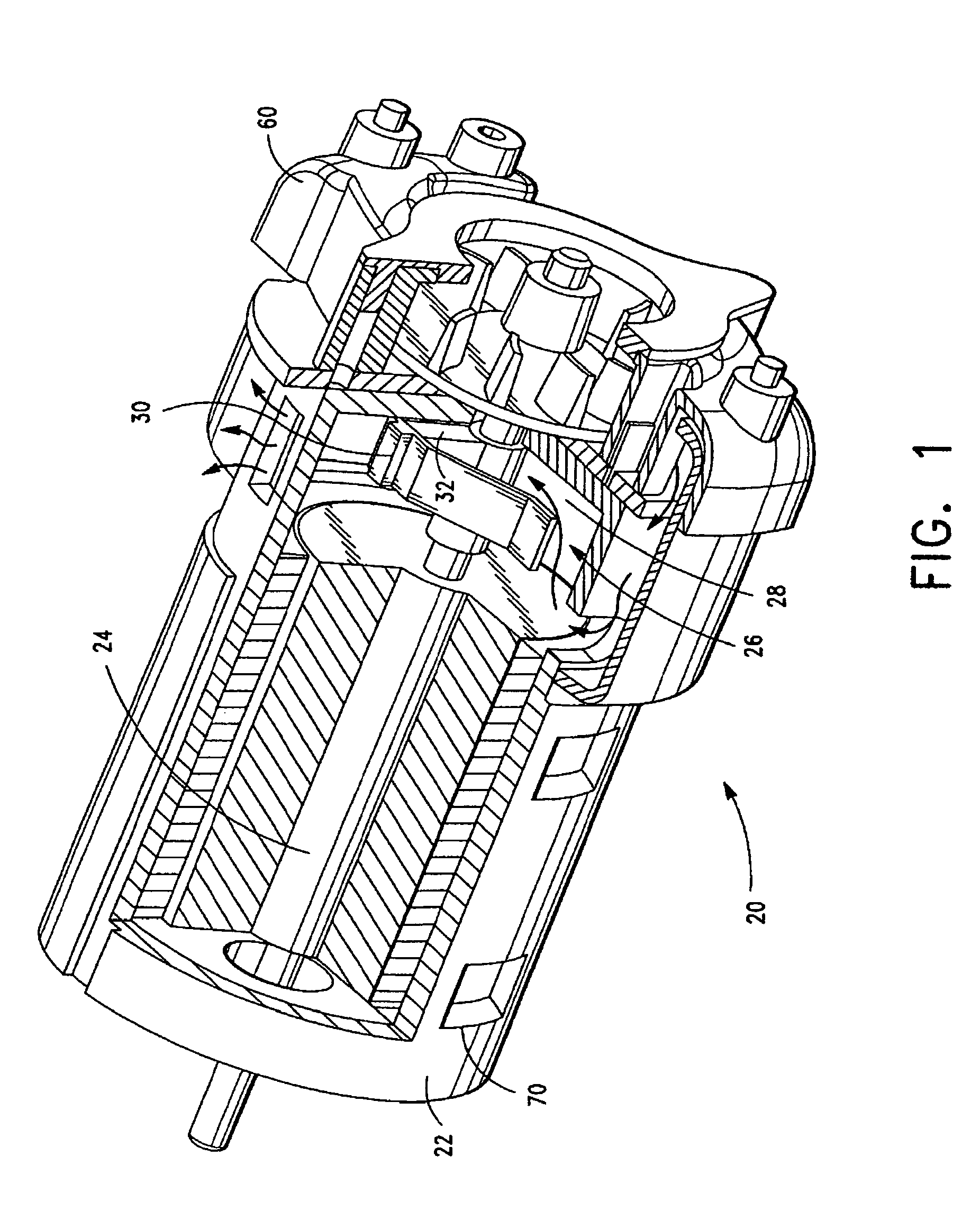
[0033]An exemplary embodiment of the electric motor in accordance with the present invention generally denoted by the numeral 20 will now be described with reference to FIG. 1. The motor 20 includes a stator 22 or housing, an armature 24 or rotor and a brush assembly, generally denoted by the numeral 26.

[0034]The armature 24 includes a commutator 28. Typically, the commutator 28 uses copper segments. However, more modern examples of the commutator 28 include graphite segments.

[0035]The brush assembly 26 includes a brush holder 30 for holding a brush 32 against the commutator 28. The area which the brush 32 contacts the commutator 28 is called the contact area.

[0036]The brush holder 30 holds the brush 32 in place and provides electrical insulation from the housing when the rotor is activated. Supplying power to the motor causes the brush 32 in contact the commutator 28 at the contact area to complete the electrical circuit and cause the armature to rotate.

[0037]The exemplary embodime...


PUM


Abstract

A high speed electric motor for use in a variety of applications. The electric motor an electric motor including a motor housing or stator, a rotor having a commutator and brushes for contacting the commutator at a predefined area known as the contact area. Additionally, the motor includes a forced air cooling assembly. The forced air cooling assembly includes a centrifugal fan for creating air flow, a manifold for accelerating the air flow. The manifold having exit ports and the exit ports being positioned directly over the contact area for directing the accelerated air flow at the contact area and the motor housing having at least one opening aligned with the contact area and at least a second opening defining an exit vent. Additionally, a method of cooling the motor in accordance with the invention is also disclosed.

Description

FIELD OF THE INVENTION[0001]This invention generally relates to the field of brushed electrical motors. More particularly, this invention relates to small, high speed electric motors which include structure for internal cooling.BACKGROUND OF THE INVENTION[0002]Electric motors are in widespread use for a seemingly never ending variety of tasks. Such motors are popular because they are small and powerful. Additionally, there is virtually zero pollution and generally speaking the motors run far more quietly than other motors, such as an internal combustion engines (ICEs). Many industries rely solely upon such electrical motors to power their devices. For example, pool cleaners are virtually exclusively powered by such motors. As will be appreciated, in order to make such devices practical, the motors must be quite small and very powerful. Such motors are required to rotate at extremely high speed and are placed in a confined spaces. As will be readily understood the physical limitation...

Claims


Application Information

Patent Timeline
Patent Type & Authority Patents(United States)
IPC IPC(8): H02K9/28H02K9/04
CPCH02K9/28H02K9/04
Inventor HUI, WING-KIN
Owner SMARTPOOL
Why Eureka
Try Eureka