
Suction nozzle for a vacuum cleaner, comprising a dust flow display device

a technology of dust flow display and vacuum cleaner, which is applied in the direction of vacuum cleaners, cleaning processes and utensils, chemistry apparatus and processes, etc., can solve the problems of unfavorable use, inability to implement, and inability to achieve practical implementation based on this design approach, so as to prevent damage to the sensor, easy to replace, and easy to be seen by users

Inactive Publication Date: 2010-10-05
MIELE & CIE KG
View PDF15 Cites 10 Cited by
  • Summary
  • Abstract
  • Description
  • Claims
  • Application Information

AI Technical Summary

Benefits of technology

[0010]It is an object of the present invention that a sensing and indicating device be accommodated in the air-flow path of the vacuum cleaner in such a manner that the components involved in the overall system are installed in a space-saving and ergonomically favorable manner. A further or alternate object is to find an installation location for the sensor, which has favorable flow characteristics and ensures trouble-free and reliable operation.
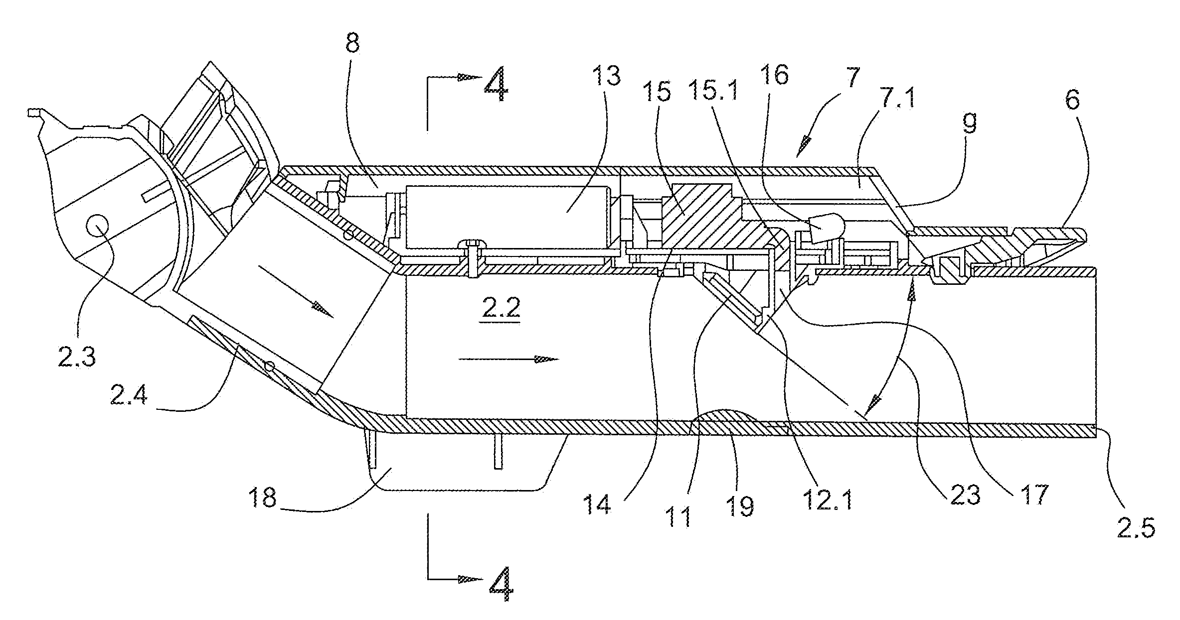
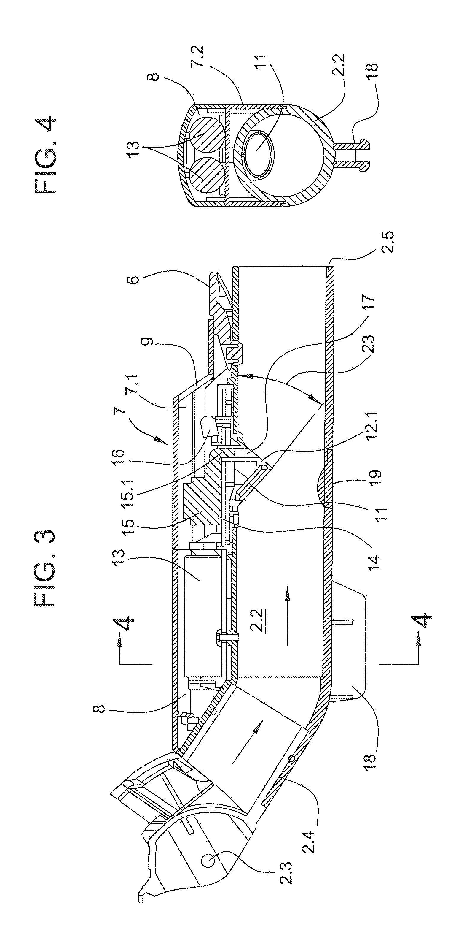
[0012]The present invention provides significant advantages. It was found that especially the upwardly directed connection part of the suction nozzles is particularly suitable for accommodating the sensor, control and indicating system.
[0013]Nevertheless, the bottom part or the suction mouth part of the suction nozzle can still be of flat construction. In addition, by forming an attachable housing on the upper side of the connection part or the upward connector member, all components can be accommodated in a manner which is ergonomically favorable and compatible with styling requirements. The battery compartment, for example, is easily accessible, and the batteries are very easy to replace. Moreover, the indicating elements, which indicate the condition of the suction air stream in the generally known manner by means of indicating LED's, can be installed such that they are easily visible to the user. This display window is always in the direct line of sight of the user, because during vacuum cleaning, he or she is always looking along the suction wand toward the suction nozzle area.
[0014]Another, particularly essential features is that the piezoelectric sensor is mounted on the lower side of the upper wall of the connection part. This decisively contributes to the special method of operation of the system. When heavy parts and particles are still present in the suction air stream, these are conveyed by the dust-air stream generally beneath the sensor and into the collecting chamber system of the vacuum cleaner. Thus, the sensor is not constantly exposed to impinging heavy particles, which helps prevent damage to the sensor. In addition, it can show its advantages when it is important. This is generally the case when the level of dust and the number of particles in the air stream become less and less as the vacuum cleaning process proceeds. Even then, the sensor can still detect minute dust particles in the air stream, which allows it to provide meaningful information to the user until a very high level of cleanliness is reached. This is very important especially for allergic persons. It is very advantageous for these people that the dust indicator according to the present invention allows detection of ultrafine dust, which is known to be allergenically very active.
[0015]Another advantage of the new system is that it includes a holding device to which all essential components are attached, such as the dust sensor, the printed circuit board containing the control device, the low-pressure switch, and the indicating elements. This makes it possible to achieve a space-saving and compact design. Furthermore, easy installation and removal during servicing are ensured because the holding device can be detachably mounted in the opening of the connection part of the suction nozzle.
[0016]Moreover, in the installed state, the system is configured such that the air inlet conduit of the pressure switch is located in the wind shadow of the holding device, thus preventing accumulation of dirt on the air inlet conduit, which would otherwise impair the proper functioning of the pressure switch.

Problems solved by technology

To remedy this, a number of proposals have been made in the patent literature, but these proposals have not yet led to any implementation that would be relevant in practice.
There is no known practical implementation based on this design approach.
Since the additional elements (sensor, battery-operated control device, and indicating devices) are accommodated directly in the bottom part of the suction nozzle, the size of the bottom part is inevitably increased.
Therefore, it is no longer possible to move such a suction nozzle into the narrow free spaces under furniture.
Moreover, in cases where the bottom part of the suction nozzle does disappear under a piece of furniture, the indicating device is no longer visible.
Furthermore, the bottom part of the suction nozzle, in particular, is inevitably exposed to strong shocks.
This may easily lead to failures of the control electronics located in the bottom part and of the sometimes fragile sensor elements.
It is not very easy to provide an optical measurement section in the confined mounting space in the flow channels of the air-conveying system of a vacuum cleaner.
Moreover, an optical measuring system is not sufficiently reliable and accurate for certain purposes.
A particular disadvantage of optical systems is that, in addition to the actual dust, they also respond to carpet fibers resulting from wear and tear of a carpet, but do not allow any conclusions about the level of cleanliness.

Method used


Image

  • Suction nozzle for a vacuum cleaner, comprising a dust flow display device
  • Suction nozzle for a vacuum cleaner, comprising a dust flow display device
  • Suction nozzle for a vacuum cleaner, comprising a dust flow display device

Examples


Embodiment Construction

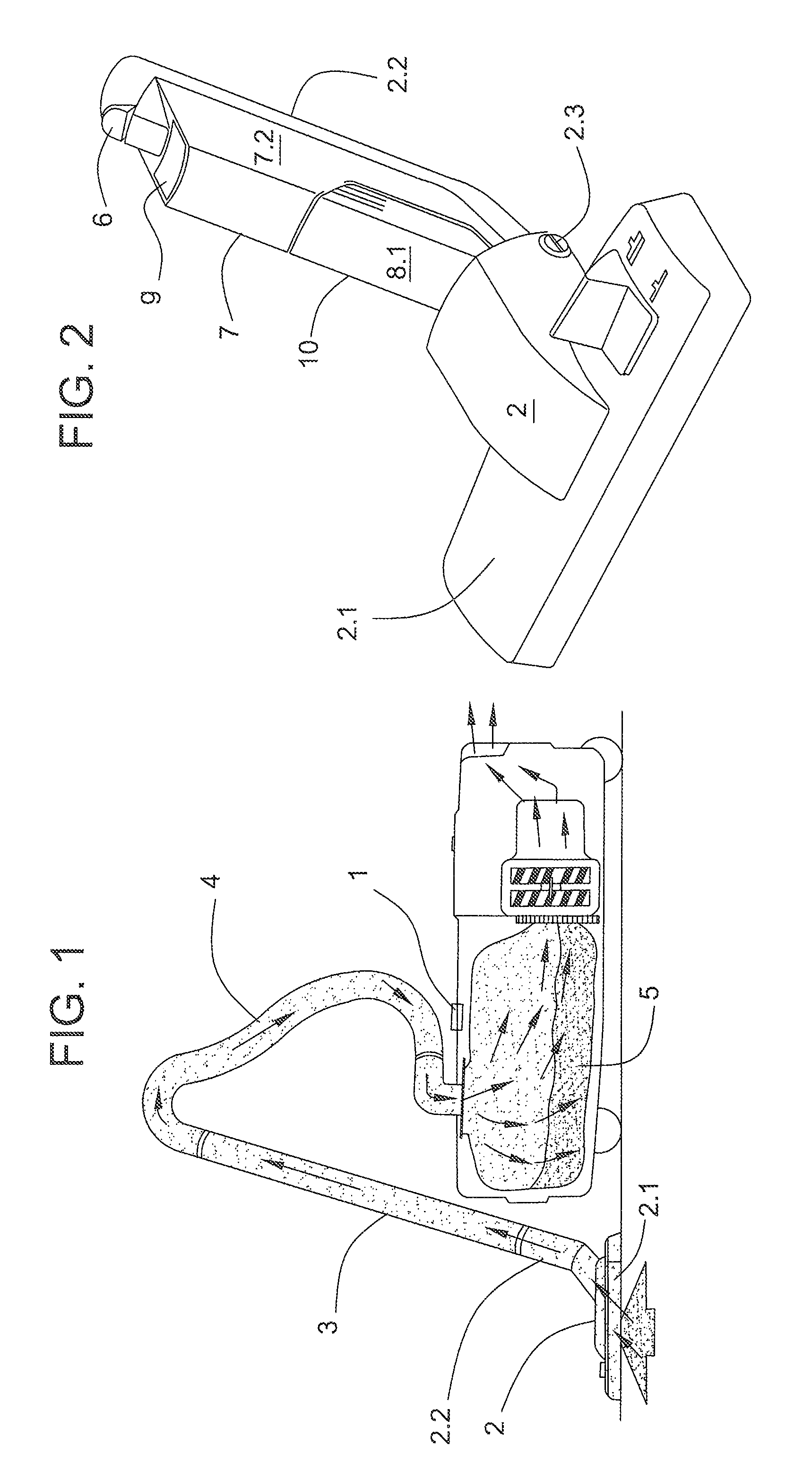
[0023]The schematic view of FIG. 1 shows vacuum cleaner (1) having a suction nozzle (2), a rigid suction wand (3), and a flexible suction hose (4) through which the dust-laden air is conveyed in the direction of the arrows into dust-collecting chamber (5). Usually, suction nozzle (2) is detachably connected to suction wand (3). In the example shown, suction nozzle (2) is a floor nozzle and is substantially formed by suction mouth part or nozzle part (2.1) and connection part (2.2). Nozzle part (2.1) and connection part (2.2) are typically connected to each other by a so-called “tilt and turn joint” mounted in coupling part (2.3).

[0024]A suction nozzle designed in accordance with the present invention is shown in detail in FIG. 2. Here too, the nozzle part (2.1) of suction nozzle (2) is connected by the tilt and turn joint mounted in coupling part (2.3) to connection part (2.2), which serves as a connector member. Connection part (2.2) is provided at its upper end with a locking hand...


PUM


Abstract

A suction nozzle for a vacuum cleaner that can be connected to a suction pipe and / or a suction tube of the vacuum cleaner includes a nozzle part that can be connected to the suction pipe or the suction tube by means of a tubular connection part. A dust sensor is arranged in the flow path of the vacuum cleaner, the signals thereof being evaluated by a battery-operated electronic control device that can be activated by a low-pressure switch. During operation, said control device controls a display device displaying the dust flow. The control device, the low-pressure switch, the display elements displaying the dust flow, and a battery compartment for receiving the batteries are arranged in a housing formed on the upper side of the tubular connection part. The dust sensor is arranged beneath the housing, inside the upper region of the connection part, in the dust air stream.

Description

CROSS-REFERENCE TO PRIOR APPLICATION[0001]This application is a U.S. National Phase of International Patent Application No. PCT / EP2005 / 000944, filed Feb. 1, 2005, which claims priority to German Patent Application No. DE 10 2005 007 677.4, filed Feb. 16, 2004, the entire disclosure of which is incorporated by reference herein. The International Application was published in German on Aug. 25, 2005 as WO 2005 / 077243.FIELD OF THE INVENTION[0002]The present invention relates to a suction nozzle for a vacuum cleaner, said suction nozzle being connectable to a suction wand and / or to a suction hose of the vacuum cleaner, the suction nozzle having a nozzle part which is provided with a suction mouth and is connectable to the suction wand or to the suction hose of the vacuum cleaner via a tubular connection part, the suction nozzle including a dust-flow sensor which is disposed in the flow path of the vacuum cleaner and whose signals are analyzed by an electronic control device, and, during ...

Claims


Application Information

Patent Timeline
Patent Type & Authority Patents(United States)
IPC IPC(8): A47L7/00A47L9/02A47L9/28
CPCA47L9/02A47L9/281A47L9/2857
Inventor ANDRUP, KLEMENSBECKER, DIETHARDKARA, SEYFETTINLIEBIG, OLIVERSCHULTZ, RAINERSTORK, HEIKOTIEKOETTER, STEFANWOLF, CORNELIUS
Owner MIELE & CIE KG
Learn More