Control apparatus for vehicular drive system

a control apparatus and power transmission technology, applied in the direction of electric propulsion mounting, battery/cell propulsion, gearing, etc., can solve the problems of limited size reduction and prior art techniques suffer from difficulty in effectively reducing the overall length of the power transmission system

Inactive Publication Date: 2010-10-12
TOYOTA JIDOSHA KK +1
View PDF10 Cites 36 Cited by
  • Summary
  • Abstract
  • Description
  • Claims
  • Application Information

AI Technical Summary

Benefits of technology

[0016]In the vehicular power transmitting system constructed according to the above-described mode (1) which is a first aspect of this invention, the support member for supporting the rotor of the electric motor includes the support portion formed in its one axial end portion, at which the rotor is supported rotatably about its axis, and the tapered portion having the diameter increasing in the axial direction from the above-indicated one axial end portion to the other axial end portion at which the support member is fixed to the casing. The winding portion of the stator of the electric motor is disposed in the space formed radially outwardly of the tapered portion, while the fluid passage portion for supplying the working fluid to the frictional coupling devices of the transmission portion is disposed in the space formed radially inwardly of the tapered portion. The provision of the support member including the tapered portion permits reduction of the axial dimension of the vehicular power transmitting system as compared with that of the prior art vehicular power transmitting system in which the support member does not include a tapered portion. Thus, the present mode (1) of the invention provides a vehicular power transmitting system the overall axial dimension of which can be effectively minimized.
[0065]The vehicular power transmitting system according to the above-described mode (19) has the same advantage as described above with respect to the above-described mode (8).

Problems solved by technology

Although the prior art techniques described above permit some degree of reduction of the size of the vehicular power transmitting system, the size reduction is limited.
In particular, the prior art techniques suffer from difficulty to effectively reduce the overall length of the power transmitting system, namely, its dimension in the axial direction of the input and output shafts.

Method used


Image

  • Control apparatus for vehicular drive system
  • Control apparatus for vehicular drive system
  • Control apparatus for vehicular drive system

Examples


Embodiment Construction

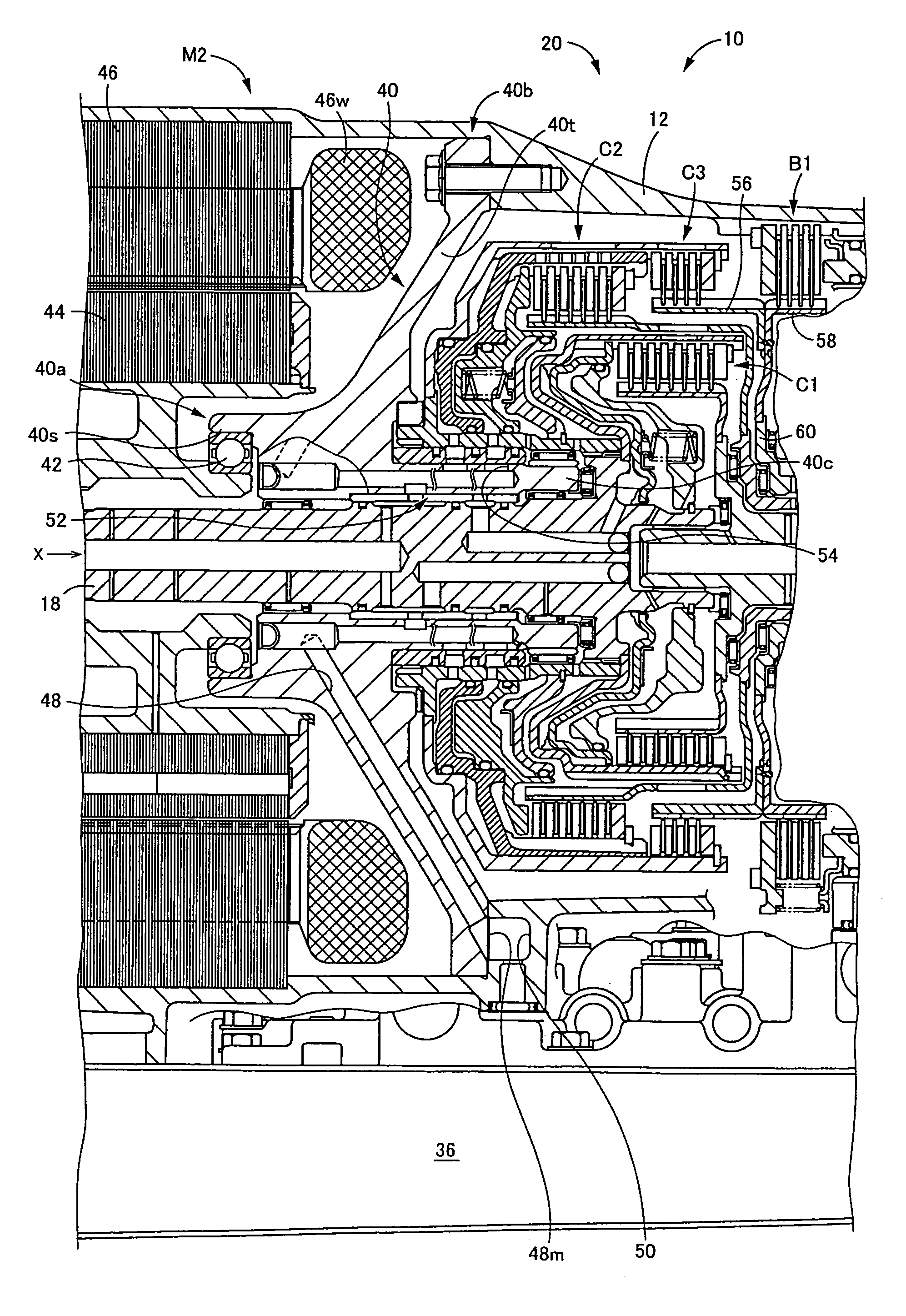
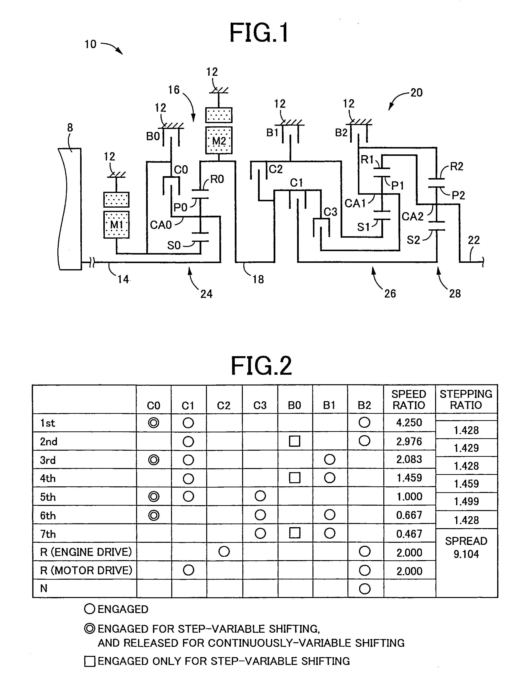
[0077]Referring first to the schematic view of FIG. 1, there is shown a vehicular power transmitting system 10 constructed according to one embodiment of the present invention. This power transmitting system 10 constitutes a part of a drive system for a hybrid vehicle, which drive system includes a drive power source in the form of an engine 8 that is an internal combustion engine such as a gasoline engine or a diesel engine. As shown in FIG. 1, the power transmitting system 10 includes: a stationary member in the form of a transmission casing 12 (hereinafter referred to simply as “casing 12”) which is attached to a body of the hybrid vehicle and which is formed integrally with a structure of a hydraulic control unit 36 shown in FIG. 9); an input rotary member in the form of an input shaft 14 connected directly, or indirectly via a pulsation absorbing damper or vibration damping device (not shown) to the engine 8; a differential device in the form of a power distributing mechanism 1...


PUM


Abstract

A vehicular power transmitting system including a transmission portion constituting a part of a power transmitting path, an electric motor connected to the power transmitting path, an electrically controlled differential portion connected to the electric motor and having a differential state controllable according to a change of an operating speed of the electric motor, a casing accommodating the transmission portion, the electric motor and the electrically controlled differential portion, and a support member for supporting a rotor of the electric motor, the support member including a support portion formed in one axial end portion thereof, at which the rotor is supported rotatably about its axis, and a tapered portion having a diameter increasing in an axial direction from the one axial end portion toward the other axial end portion at which the support member is fixed to the casing, and wherein a winding portion of a stator of the electric motor is disposed in a space formed radially outwardly of the tapered portion, while a fluid passage portion for supplying a working fluid to frictional coupling devices of the transmission portion is disposed in a space formed radially inwardly of the tapered portion.

Description

This is a Continuation of Application No. 12 / 216,415 filed Jul. 3, 2008. The disclosure of the prior application is hereby incorporated by reference herein in its entirety.[0001]The present application claims the benefits of Japanese Patent Application No. 2007-179082 filed Jul. 6, 2007, the disclosure of which is herein incorporated by reference in its entirety.BACKGROUND OF THE INVENTION[0002]1. Field of the Invention[0003]The present invention relates in general to a vehicular power transmitting system, and more particularly to an improvement of the system for reducing its size.[0004]2. Discussion of Prior Art[0005]There is known a vehicular power transmitting system including (a) a transmission portion constituting a part of a power transmitting path, and (b) an electrically controlled differential portion connected to the electric motor, and having a differential state between rotating speeds of its input and output shafts, which differential state is controllable according to ...

Claims


Application Information

Patent Timeline
Patent Type & Authority Patents(United States)
IPC IPC(8): F16H57/02B60K6/26B60K6/365B60K6/40B60K6/405B60K6/445B60K6/543B60K6/547B60K17/04F16H57/021F16H57/023F16H57/04
CPCB60K1/00B60K6/365B60K6/405B60K6/445B60K6/547B60L11/123B60L11/14B60W10/06B60W10/08B60W10/115B60W20/00F16H3/728Y10T74/2186B60L2240/16B60L2240/26B60L2240/421B60L2240/441B60L2240/445B60L2240/485B60W2510/0638B60W2510/0676B60W2510/068B60W2510/081B60W2510/107B60W2510/244B60W2520/10B60W2520/105B60W2520/28B60W2530/10B60W2540/10B60W2540/12B60W2710/0605B60W2710/081F16H2037/0873F16H2200/0056F16H2200/201F16H2200/2048Y02T10/6217Y02T10/6286Y02T10/642Y02T10/7077Y02T10/6239Y10S903/952B60K1/02B60L50/16B60L50/61Y02T10/62Y02T10/64Y02T10/70Y02T10/7072
Inventor IWASE, YUJIKOJIMA, MASAHIROIBARAKI, RYUJITABATA, ATSUSHIIMAMURA, TATSUYAKAKINAMI, TAKUMASADA, NATSUKIATARASHI, TOMOOIKE, NOBUKAZU
Owner TOYOTA JIDOSHA KK
Why Eureka
Try Eureka