Method and apparatus for treating substrates in a rotary installation

a technology of substrate and rotary installation, which is applied in the direction of electrodes, ion implantation coatings, chemical vapor deposition coatings, etc., can solve the problems of inability to vary the process sequence in any way, drop in the quality of coating, etc., and achieve the effect of increasing throughput and maintaining the process parameters of coating

Active Publication Date: 2010-10-12
SCHOTT AG
View PDF5 Cites 10 Cited by
  • Summary
  • Abstract
  • Description
  • Claims
  • Application Information

AI Technical Summary

Benefits of technology

[0047]In addition to the setting of the angle sections described above, it is in this context also possible for the angle position at the start of the process phase—“evacuation of the interior of the hollow body as far as a second pressure value”—to be set variably, as a function of the current rotational speed of the rotor, with respect to the angle position at the start of the process phase—“evacuation of the treatment device in the region of the space outside the hollow body as far as a first pressure value”—so that a fixed delay time is realized between these process phases. This ensures, irrespective of fluctuations in the rotational speed of the rotor, that the pressure difference between the pressure in the interior of the hollow body and the pressure in the treatment chamber remains identical and the process parameters for the coating are kept stable.
[0048]If all the treatment devices are connected to at least one common pump device via distributor lines, the pump device can be fixedly connected to the treatment devices, and an increased throughput can be realized. In this embodiment, the pump device can also rotate on the rotor, which means that there is no need for a complex rotating connection, which is difficult to seal, or a pump-side rotary slide leadthrough.

Problems solved by technology

Therefore, it is not possible to vary the process sequence in any way.
This has an adverse effect in particular in the event of disruptions and fluctuations in the process sequence, since it is not possible to react flexibly to such events, which can lead to a drop in the quality of coating.

Method used


Image

  • Method and apparatus for treating substrates in a rotary installation
  • Method and apparatus for treating substrates in a rotary installation
  • Method and apparatus for treating substrates in a rotary installation

Examples


Embodiment Construction

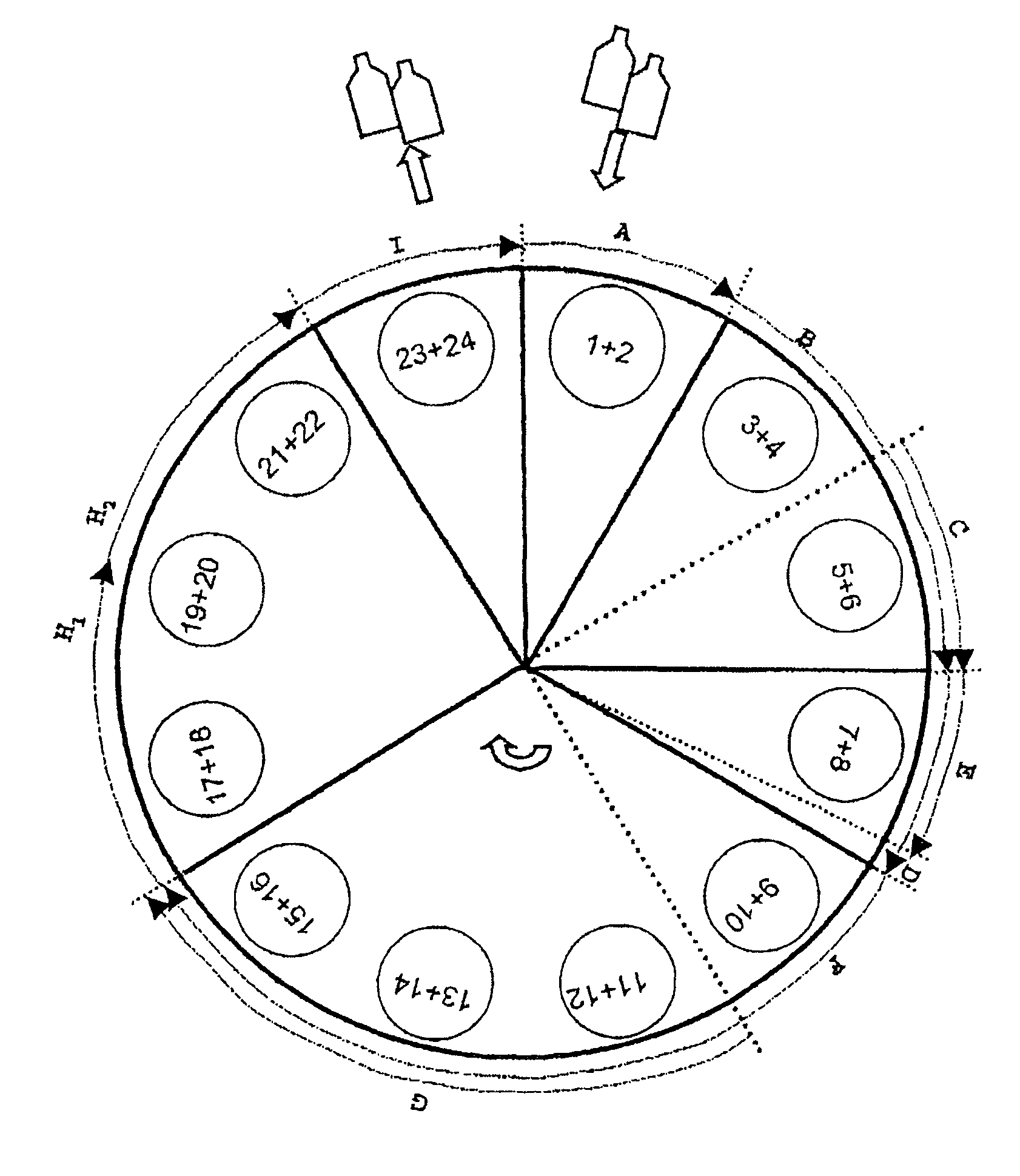
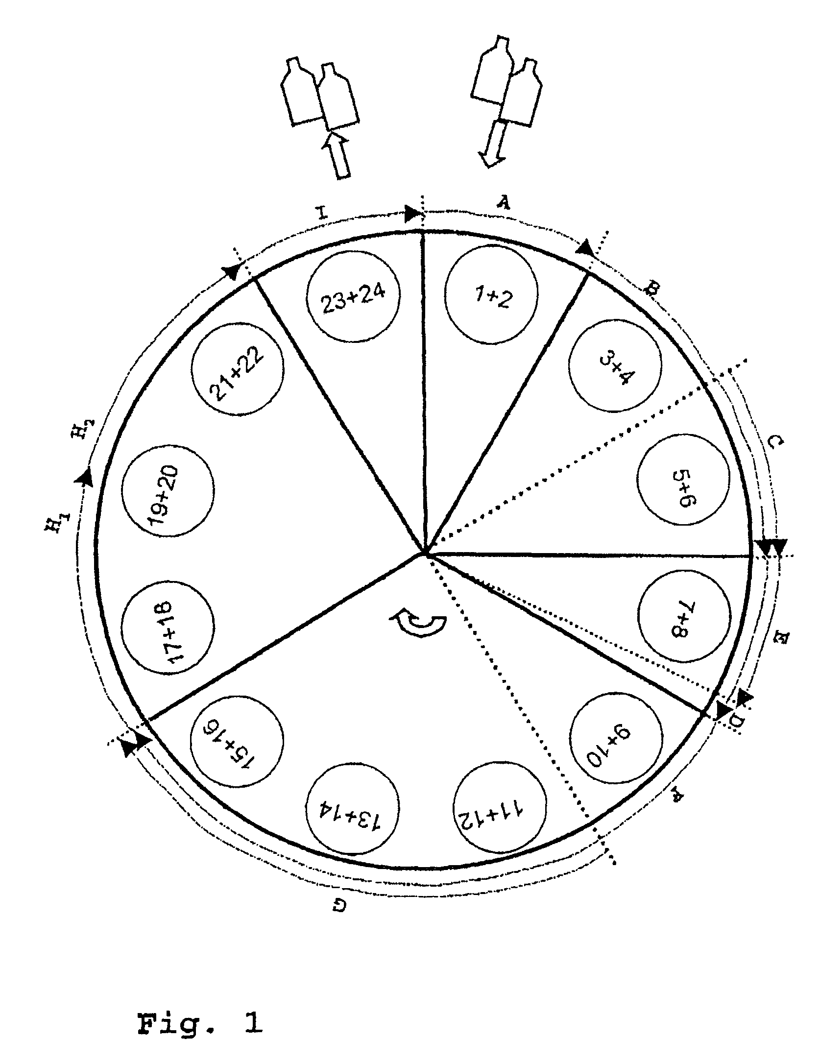
[0061]The diagrammatic illustration of the process sequence of an operation for coating hollow bodies (1, 2, . . . , 24) shown in FIG. 1 shows the individual process phases (A, B, . . . , I) and the corresponding angle sections on the rotor. Angle sections illustrated by solid lines are fixed angle sections. The angle sections illustrated by dotted lines can be set variably as a function of the current rotational speed of the rotor. Twelve identical treatment stations (101, 102, . . . , 112) are arranged at regular intervals of 30° on the rotor. Each treatment station (101, 102, . . . , 112) passes through the entire treatment cycle comprising the process phases (A, B, . . . , I) and the correspondingly associated angle sections:[0062]introduction of the hollow bodies (A),[0063]evacuation of the treatment device in the region of the space outside the hollow body (B),[0064]evacuation of the interior of the hollow bodies (C),[0065]supplying of process gas for bonding agent (D),[0066]i...


PUM

PropertyMeasurementUnit
angleaaaaaaaaaa
angleaaaaaaaaaa
rotational speedaaaaaaaaaa

Abstract

The invention relates to a method and an apparatus for the treatment of substrates, in particular for the coating of plastic containers on a rotary installation. A plurality of treatment devices are arranged on the rotor and pass through a plurality of process phases as a function of their angle position on the rotor. For at least one process phase, the angle position can be set variably as a function of the current rotational speed of the rotor.

Description

CROSS-REFERENCE TO RELATED APPLICATIONS[0001]This application claims the benefit under 35 U.S.C. §119(a) of German Application Serial No. 10-2004-028369.9-45, filed Jun. 9, 2004, the entire contents of which are incorporated by reference herein.BACKGROUND OF THE INVENTION[0002]1. Field of the Invention[0003]The invention relates to a method and an apparatus for treating substrates in a rotary installation, in particular for the uniform barrier coating of plastic containers in a rotary installation.[0004]2. Description of Related Art[0005]The processes for coating mass-produced products, such as for example food or pharmaceutical packaging material, plastics drinks bottles, etc., require high throughput with a high coating quality for industrial manufacture.[0006]The plastics materials which are more and more often being used for these products have barrier coatings in order to reduce their permeability to gases and liquids and to protect them from chemical attacks or UV radiation. I...

Claims


Application Information

Patent Timeline
Patent Type & Authority Patents(United States)
IPC IPC(8): C23C16/00B05D7/22B65D23/02C22F1/04C23C16/02C23C16/04C23C16/40C23C16/50C23C16/511C23C16/54
CPCC23C16/0272C23C16/045C23C16/401C23C16/54
Inventor BICKER, MATTHIASBEHLE, STEPHANLUETTRINGHAUS-HENKEL, ANDREASARNOLD, GREGORKLEIN, JUERGEN
Owner SCHOTT AG
Why Eureka
Try Eureka