Power supply apparatus having switchable switching regulator and linear regulator

a technology of switching regulator and power supply apparatus, which is applied in the direction of electric variable regulation, process and machine control, instruments, etc., can solve the problem of needlessly consuming electric power, and achieve the effect of efficient switching

Active Publication Date: 2010-10-12
ROHM CO LTD
View PDF24 Cites 22 Cited by
  • Summary
  • Abstract
  • Description
  • Claims
  • Application Information

AI Technical Summary

Benefits of technology

[0018]According to this embodiment, on the one hand, in a short-term light load state, high efficiency can be realized by a compulsory OFF circuit, and in a long-term light load state, efficiency of the power supply apparatus can be improved by halting the switching regulator and making only the linear regulator operate.
[0025]By monitoring the output current of the linear regulator, since, when there is a transition from the light load state to the heavy load state, it is possible to switch immediately to the switching regulator, the load in the heavy load state can be prevented from being driven by the linear regulator, and it is possible to realize high efficiency.
[0031]According to this embodiment, by preferably switching, in accordance with load state, the output voltage of the switching regulator and the linear regulator, by the control circuit, it is possible to reduce consumed current of the entire electrical power unit.
[0033]According to this embodiment, since the step down switching regulator and the linear regulator can be preferably switched, when the current flowing in the microcomputer varies, it is possible to realize long life for the battery.

Problems solved by technology

This current is not supplied to the load, and since it is supplied from an output capacitor, electrical power is needlessly consumed.

Method used


Image

  • Power supply apparatus having switchable switching regulator and linear regulator
  • Power supply apparatus having switchable switching regulator and linear regulator
  • Power supply apparatus having switchable switching regulator and linear regulator

Examples


Embodiment Construction

[0048]The invention will now be described based on preferred embodiments which do not intend to limit the scope of the present invention but exemplify the invention. All of the features and the combinations thereof described in the embodiment are not necessarily essential to the invention.

[0049]Below, the present invention will be explaining based on a preferred embodiment, referring to the drawings. Similar or equivalent component elements, members, and processes shown in respective figures are given the same reference symbols, and repeated explanations are omitted as appropriate. Furthermore, the embodiments are examples that do not limit the invention, and all of the features and combinations thereof, described in the embodiments, are not necessarily essential items of the invention.

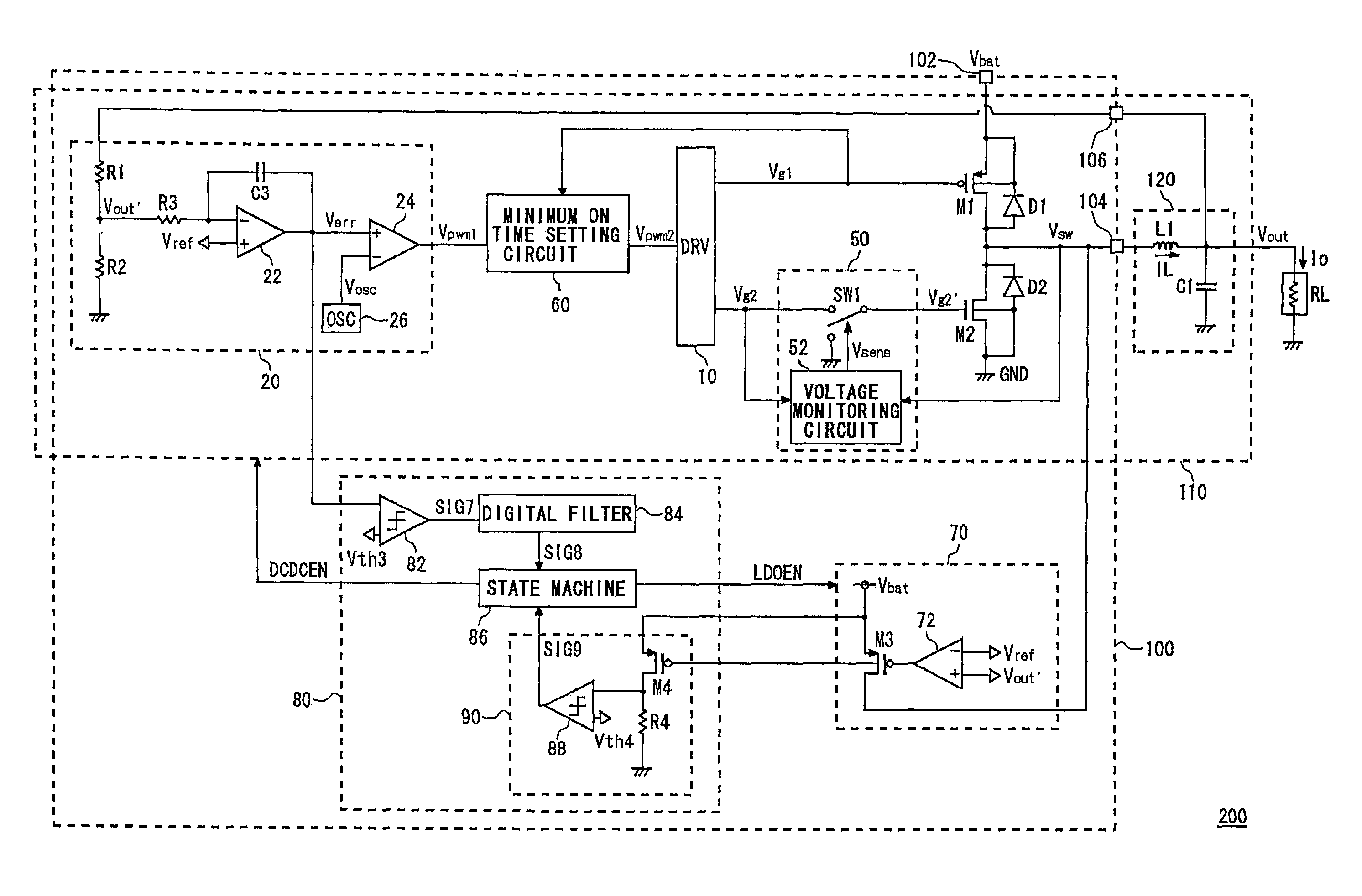
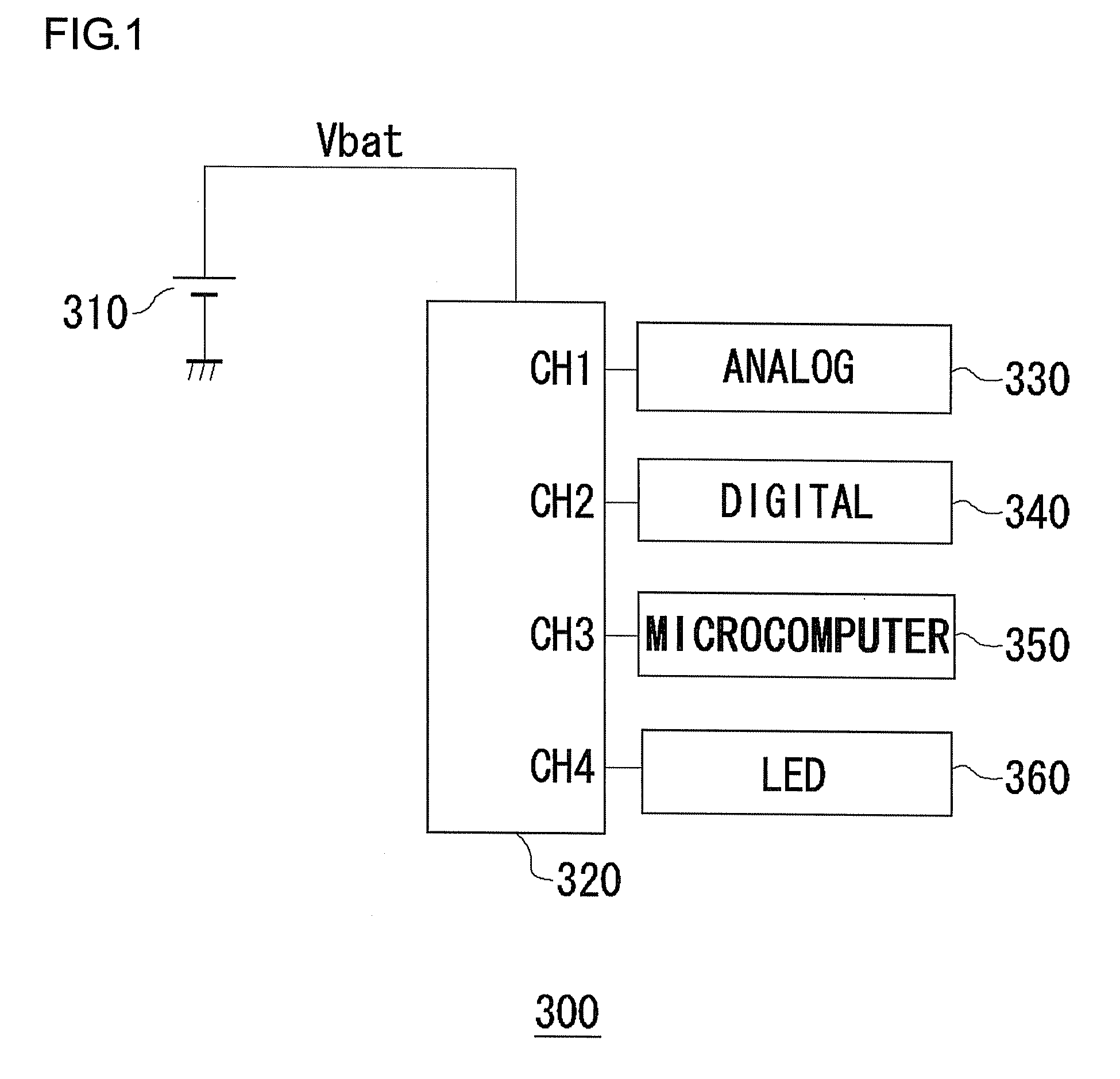
[0050]FIG. 1 is a block diagram showing a configuration of an electronic device in which a step down switching regulator according to the present embodiment is installed. The electronic device 300 is,...


PUM


Abstract

A control circuit is provided in which two power sources can be efficiently switched, for a power supply apparatus provided with a step down switching regulator and a linear regulator. A PWM controller generates a pulse width modulation signal with which a duty ratio is controlled so that output voltage of the switching regulator approaches a predetermined reference voltage. A compulsory OFF circuit monitors a switching voltage, and when a first threshold voltage is exceeded, switches a synchronous rectifier transistor OFF. A minimum ON time setting circuit limits the duty ratio of the pulse width modulation signal, so that ON time of the switching transistor is longer than a predetermined minimum value. A selector circuit monitors an error voltage, and when a predetermined state continues for a predetermined first period, puts the linear regulator in an operating state, and the step down switching regulator in a halt state.

Description

CROSS REFERENCE TO RELATED APPLICATIONS[0001]This is a U.S. national stage of application No. PCT / JP2006 / 310457, filed on 25 May 2006. Priority under 35 U.S.C. §119(a) and 35 U.S.C. §365(b) is claimed from Japanese Application No. 2005-154238, filed 26 May 2005, the disclosure of which is also incorporated herein by reference.BACKGROUND OF THE INVENTION[0002]1. Field of the Invention[0003]The present invention relates to a power supply apparatus provided with a step down switching regulator and a linear regulator, and in particular to control technology for switching the switching regulator and the linear regulator.[0004]2. Description of the Related Art[0005]In recent years, microcomputers for performing digital signal processing are being installed in various electronic devices, such as mobile telephones, PDAs (Personal Digital Assistants), laptop personal computers, and the like. Power supply voltage necessary for driving these microcomputers decreases as semiconductor manufactur...

Claims


Application Information

Patent Timeline
Patent Type & Authority Patents(United States)
IPC IPC(8): G05F1/59G05F1/56H02M3/155
CPCH02M3/1588H02M2001/0032Y10T307/724Y02B70/1466Y02B70/16H02M2001/0045Y02B70/10H02M1/0045H02M1/0032
Inventor WATANABE, HIROYUKIYAMAMOTO, ISAO
Owner ROHM CO LTD
Why Eureka
Try Eureka