
Optical device with a steerable light path

a technology of optical devices and light paths, applied in the direction of optical elements, instruments, using reradiation, etc., can solve the problems of reducing the quality of optical components, the requirement for large windows, and the size of windows, so as to reduce the weight of the steering structure and reduce the effect of chromatic aberration

Active Publication Date: 2010-10-12
RAYTHEON CO
View PDF23 Cites 27 Cited by
  • Summary
  • Abstract
  • Description
  • Claims
  • Application Information

AI Technical Summary

Benefits of technology

Enables a compact, lightweight optical device with reduced window size and low chromatic aberration, suitable for multi-wavelength applications, reducing weight and radar signatures while maintaining effective beam steering.

Problems solved by technology

The requirement for a large window has several undesirable effects.
First, the larger the window, the more expensive it is to produce with the required high optical quality.
Some possible steering approaches can in principle reduce the window size, but have so much chromatic aberration that they are satisfactory only for a single wavelength or a narrow wavelength band.

Method used


Image

  • Optical device with a steerable light path
  • Optical device with a steerable light path
  • Optical device with a steerable light path

Examples


Embodiment Construction

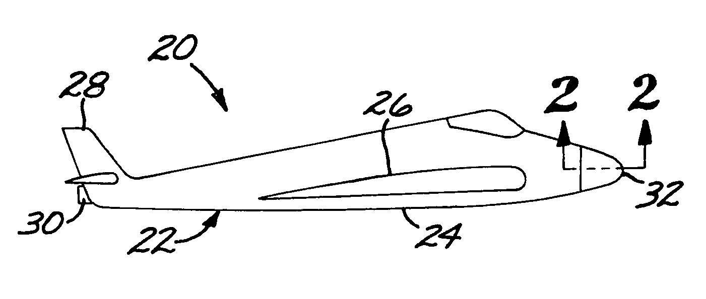
[0025]FIG. 1 depicts an aircraft 20 having a fuselage 22 with a fuselage body 24, wings 26, and a tail 28. The aircraft 20 may be unpowered or, more preferably, is powered by an engine 30, such as a gas turbine engine, a rocket engine, or an engine driving a propeller. A transparent dome window 32, here shown in the nose of the aircraft, is joined to the fuselage body 24.

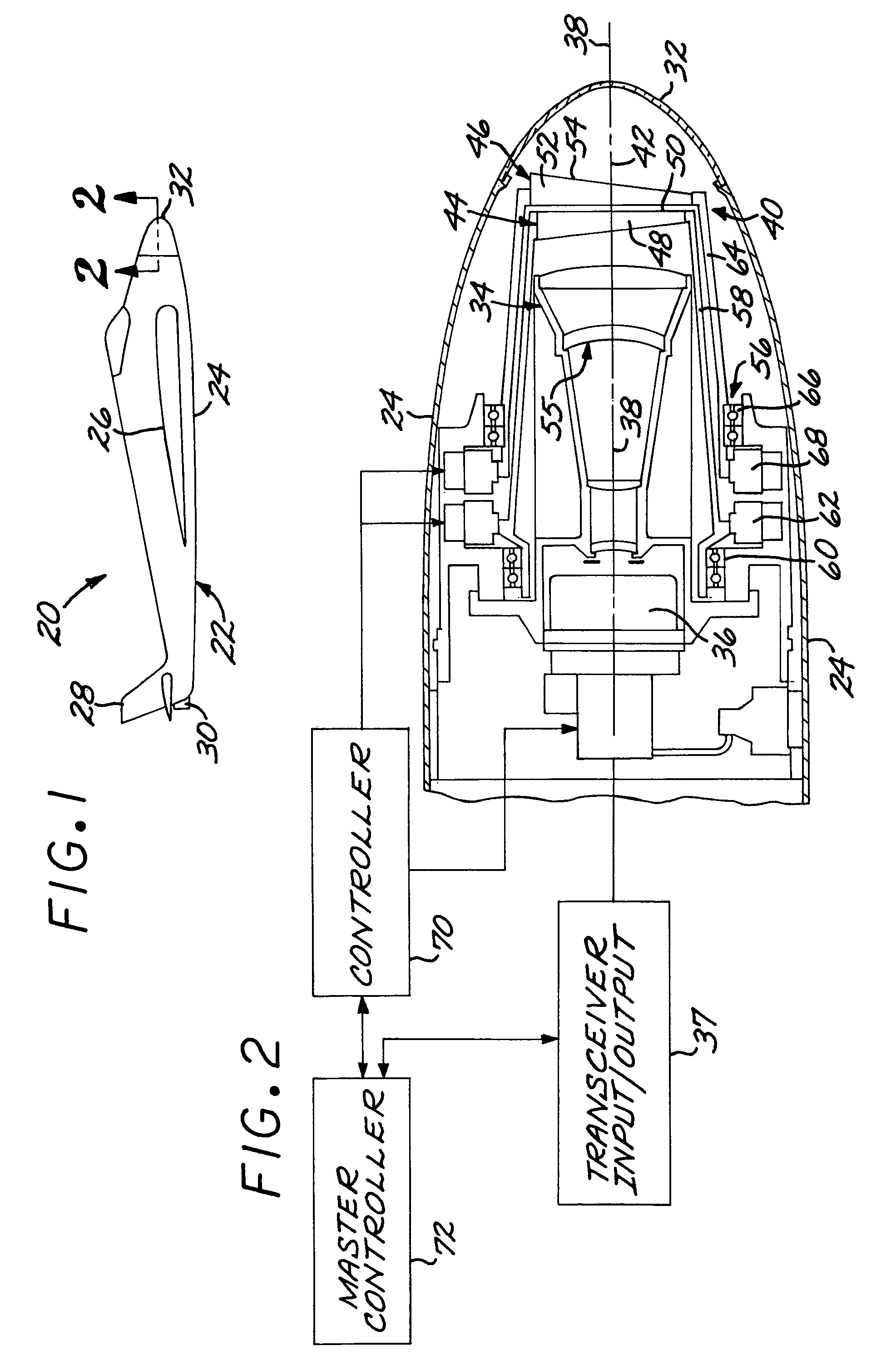
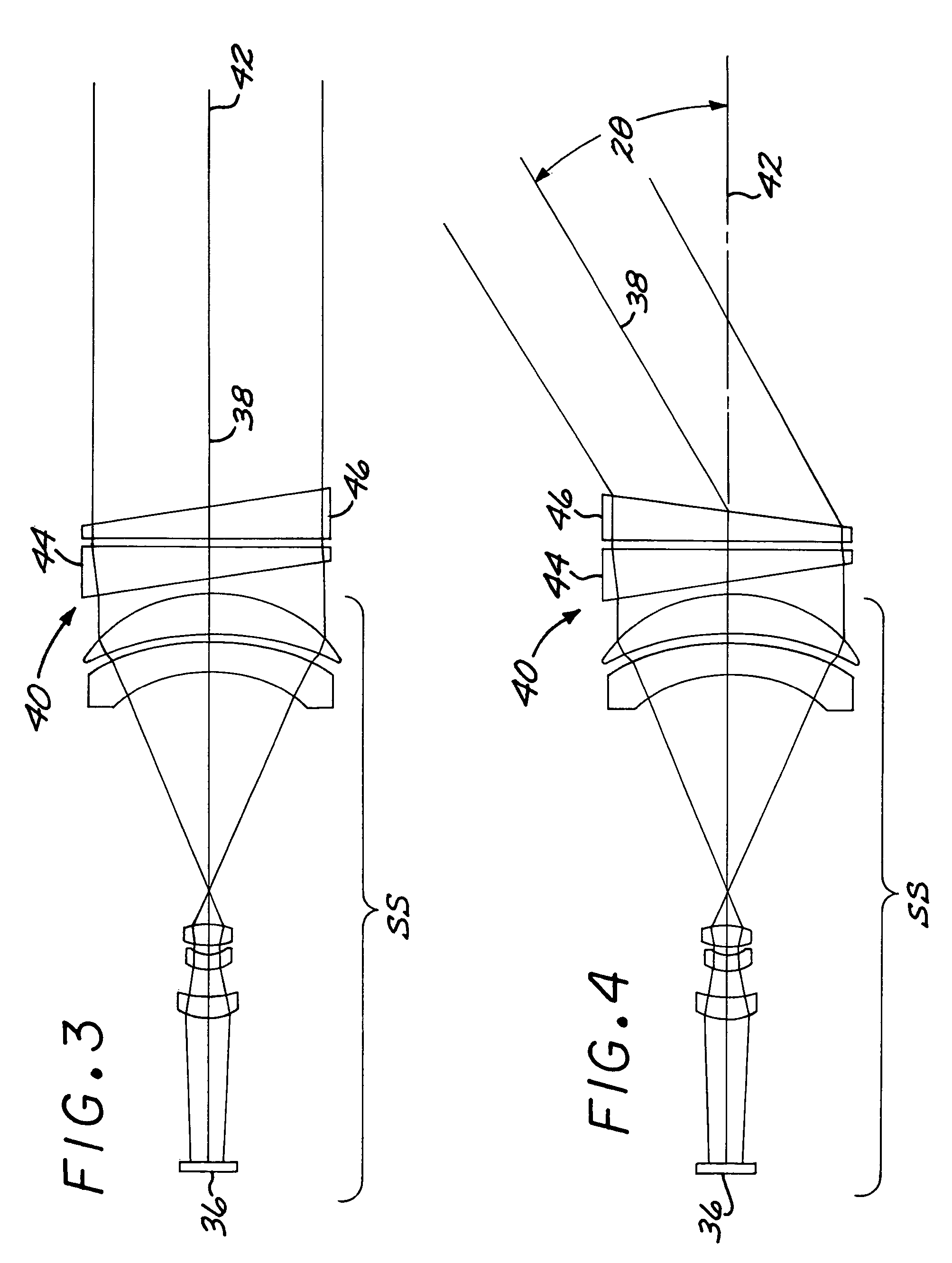
[0026]FIG. 2 is a schematic sectional view showing the interior of the fuselage 22 near the nose, and control elements. A steerable-light-path optical device 34 includes a light transceiver 36 having an external light path 38 associated therewith. The light transceiver 36 may comprise a light transmitter or a light receiver, or both. For example, the light transceiver 36 may include a laser or LED light source, or it may include a light detector. The light transceiver 36 may incorporate both functions, as for example a laser light transmitter in the form of a laser illuminator that produces an outgoing laser light b...


PUM


Abstract

A steerable-light-path optical device includes a light transceiver having an external light path associated therewith, and a path-steering device that controls the direction of the light path relative to a steering axis. The path-steering device has a first beam-deviation optical element including a first prism structure having a first diffraction grating thereon, and a second beam-deviation optical element including a second prism structure having a second diffraction grating thereon. The steering axis passes through the first and second beam-deviation optical elements. A rotational drive is operable to rotate at least one of the first beam-deviation optical element and the second beam-deviation optical element, and preferably both of the beam-deviation optical elements, about the steering axis.

Description

[0001]This invention relates to an optical device having a light transceiver that sends and / or receives a light beam and, more particularly, to the steering of the light path along which the light beam travels.BACKGROUND OF THE INVENTION[0002]Some optical devices include a light transmitter and / or a light receiver, collectively termed a light transceiver, that transmits and / or receives a light beam. The light transceiver may be pointed in a specific direction to select the direction of the light path along which the light beam that is transmitted and / or received. An example of a light transmitter is a laser rangefinder or illuminator, and an example of a light receiver is a light sensor such as a focal plane array. Some light transceivers may include both a light transmitter and a light receiver.[0003]In each case of this type of optical device, the light transceiver is pointable in a selected direction. For the case where the light transceiver is a light transmitter, the outgoing l...

Claims


Application Information

Patent Timeline
Patent Type & Authority Patents(United States)
IPC IPC(8): H04B10/00H04B10/24F41G7/22G02B5/18G02B26/08G02B27/42
CPCG01S7/4812G01S17/42G02B26/08G02B26/0808G02B26/0883G02B27/42G02B27/4211G02B27/4277
Inventor CHEN, CHUNGTE W.COOK, LACY G.
Owner RAYTHEON CO
Learn More