

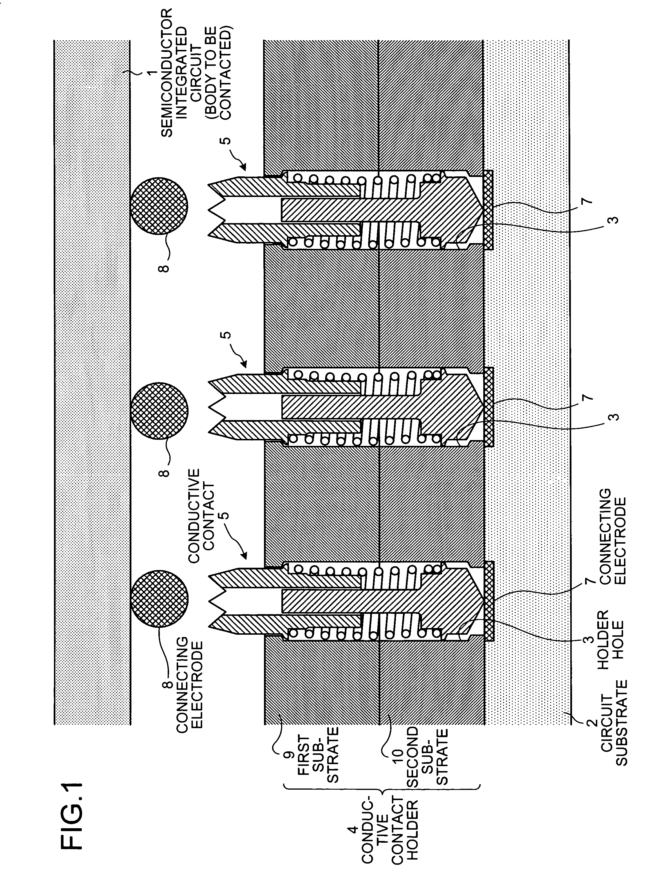
Needle-like member, conductive contact, and conductive contact unit
a technology of conductive contact and needlelike member, which is applied in the direction of individual semiconductor device testing, coupling device connection, instruments, etc., can solve the problems of difficult manufacturing cost reduction, difficult manufacturing process, and difficult manufacturing process
- Summary
- Abstract
- Description
- Claims
- Application Information
AI Technical Summary
Benefits of technology
Problems solved by technology
Method used
Image

Examples
first modified example
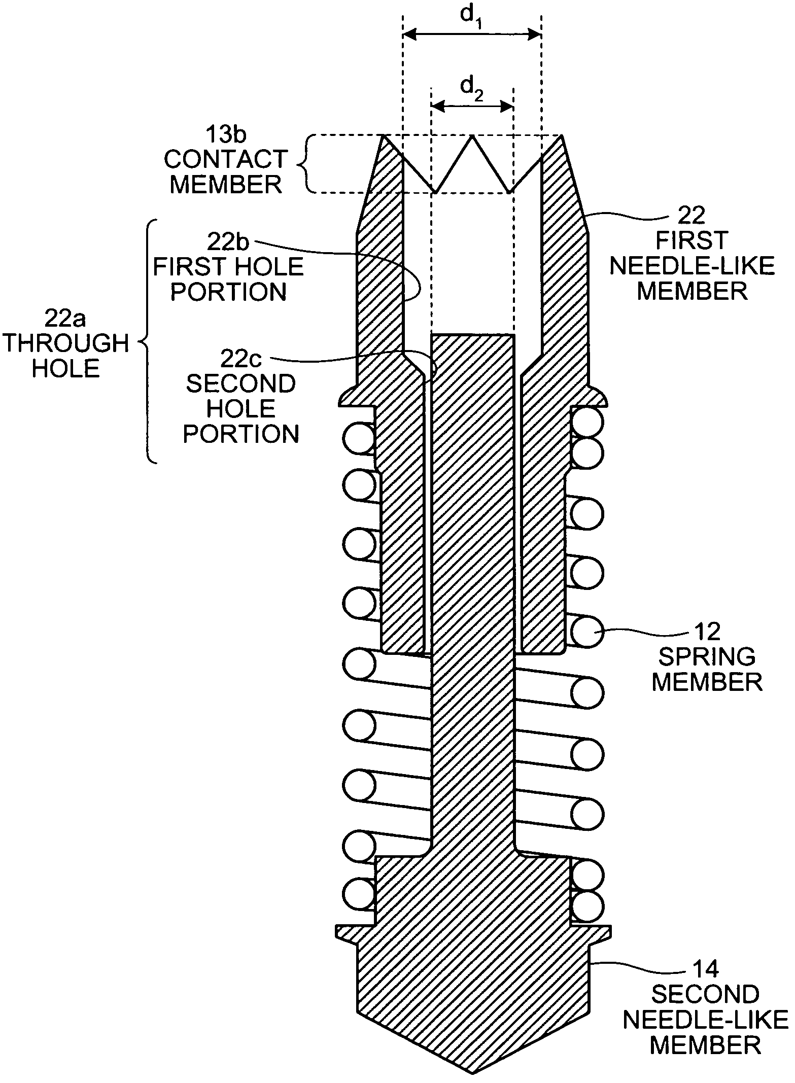
[0120]Next, a first modified example of a conductive contact unit according to the exemplary embodiment will be described. In the first modified example, an inner diameter of a through hole formed in a first needle-like member forming a conductive contact is monotonically decreasing with distance from a contact member side. The term “Monotonically decreasing” as used herein is synonymous with mathematical meaning and, specifically, it indicates that the through hole is formed so that the inner diameter becomes the same or decreases with distance from near a contact member. More specifically, “the inner diameter of the through hole is monotonically decreasing with distance from the contact member side” indicates a state where the through hole is formed so that the following relationship is formed:
[0121][Equation1]ⅆⅆxf(x)≤0(1)
where distance from the contact member is x, and the inner diameter of the through hole at a point of the distance x is f(x).
[0122]FIG. 4 is a schematic of...
second modified example
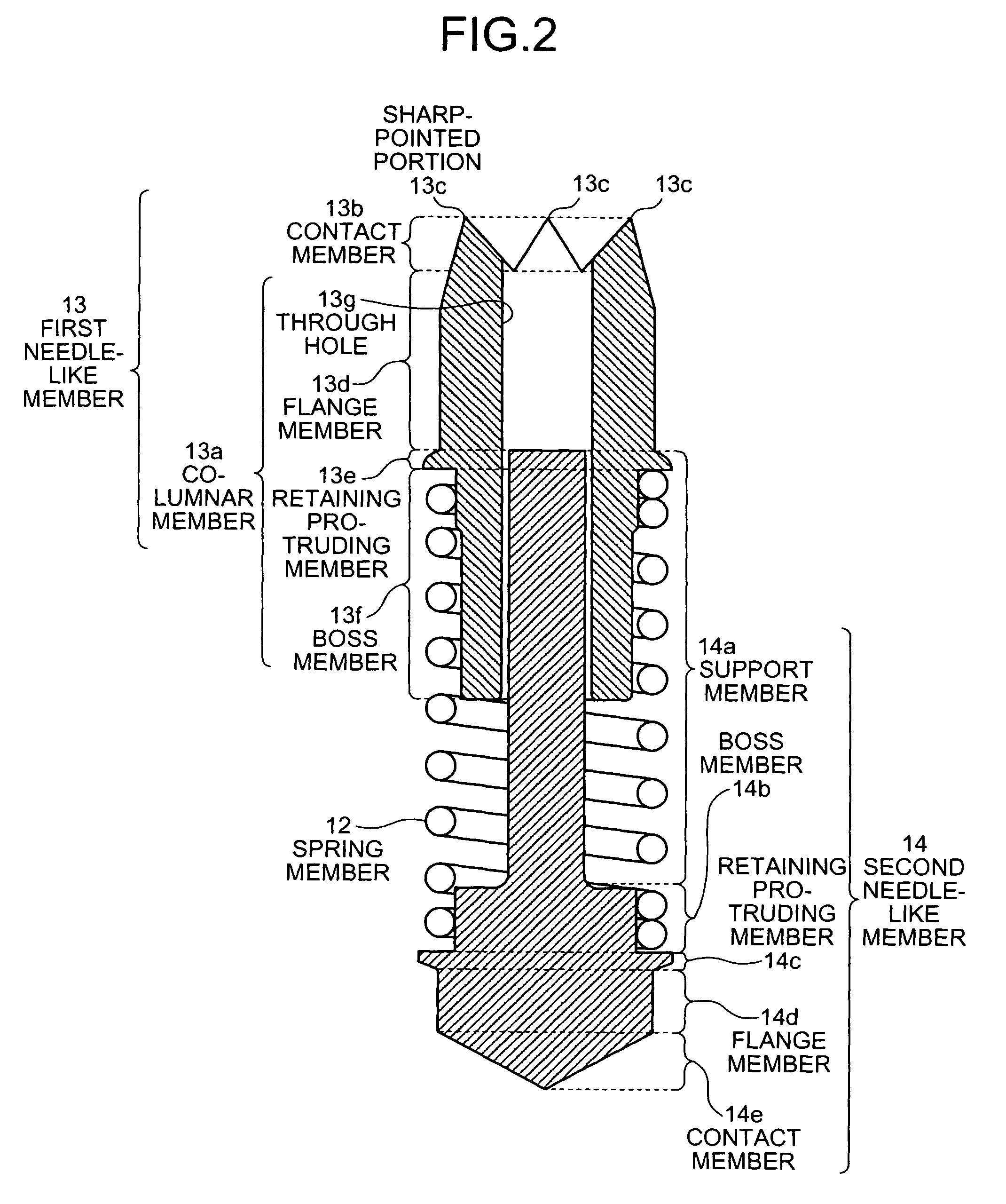
[0138]Next, a conductive contact unit according to a second modified example will be described. The second modified example is characterized by the shape of a contact member formed in a first needle-like member constituting a conductive contact. FIG. 7 is a schematic of the entire configuration of the conductive contact in the second modified example. As shown in FIG. 7, the conductive contact in the second modified example is basically similar in structure to that of the conductive contact 5 shown in FIG. 2 except that a contact member 30a formed in a first needle-like member 30 has a shape different from the one having a plurality of the sharp-pointed portions.
[0139]Specifically, as shown in FIG. 7, the contact member 30a has a shape having a spherical or paraboloid-concave surface, that is, a bowl-like shape. Even when the contact member 30a has such a shape, it is possible to electrically connect the contact member 30a to the vicinity of the peripheral portion of the connecting ...
PUM
 Abstract
Description
Claims
Application Information