Laser induced liquid jet generating device

a liquid jet and laser technology, applied in the direction of fluid jet surgical cutters, catheters, therapy, etc., can solve the problems of affecting the life of the catheter itself, hindering the flow of liquid jets from being ejected smoothly, and difficult to improve the accompanying nerve symptoms, etc., to achieve high-power laser beams, reduce the risk of patients and operators, and allow a long time of irradiation

Inactive Publication Date: 2010-10-19
MICHELIN RECH & TECH SA +1
View PDF15 Cites 13 Cited by
  • Summary
  • Abstract
  • Description
  • Claims
  • Application Information

AI Technical Summary

Benefits of technology

[0012]A laser induced liquid jet stream generating device is relatively safe for patients and operators because the catheter is protected from the laser beam's thermal effect, thus allowing long time of irradiation with a high power laser beam.
[0014]The device does not irradiate the laser beam in a narrow catheter but irradiate the laser beam in the jet generating tube unit provided at the proximal part of the catheter and introduce the generated liquid jet stream from the tip of the jet generating tube unit into the catheter, so that it is possible to use a thinner catheter as it no longer needs to have a space inside the catheter for inserting the optical fiber, thus allowing higher powered laser beam irradiation.
[0015]Moreover, since a heat transfer inhibition means is provided outside of the jet generating tube unit for preventing the thermal effect that is caused by the laser irradiating part, the heat is not transmitted to the outside even if a high power laser irradiation is applied, so that it is safe for patients and operators. Further, it provides an improved operating maneuverability, and enables to perform extremely powerful thrombi destruction operation more securely and for long hours. Furthermore, even if a drug solution is used, cooling the vicinity of the laser irradiation part of the jet generating tube unit effectively prevents the temperature of the drug solution in the vicinity to rise excessively and maintains the activity of the drug solution without being affected.

Problems solved by technology

In particular, while it is believed that the accompanying nerve symptom becomes difficult to be improved if an ischemic condition lasts for more than six hours, an extremely high recovery effect can be expected if the resumption of blood flow occurs within a few hours of the crisis.
This may hinder the liquid jet stream from being ejected smoothly and shorten the life of the catheter itself.
There is also a concern that the heat that melts or deforms resins or metals may affect blood vessels as well.
Patients and operators who accidentally touch the laser irradiation part that has turned very hot can get burned.
A high power laser beam and the high temperature caused by it can expedite the deterioration of the material in the neighborhood of the laser irradiation part, eventually damaging the device.
Moreover, if a drug solution containing a drug such as thrombi solvent is used as the liquid to be irradiated with a laser beam to generate a jet stream, the high heat generated as a result of the laser irradiation may reduce or eliminate the efficacy of the drug in the drug solution.

Method used


Image

  • Laser induced liquid jet generating device
  • Laser induced liquid jet generating device
  • Laser induced liquid jet generating device

Examples


first embodiment

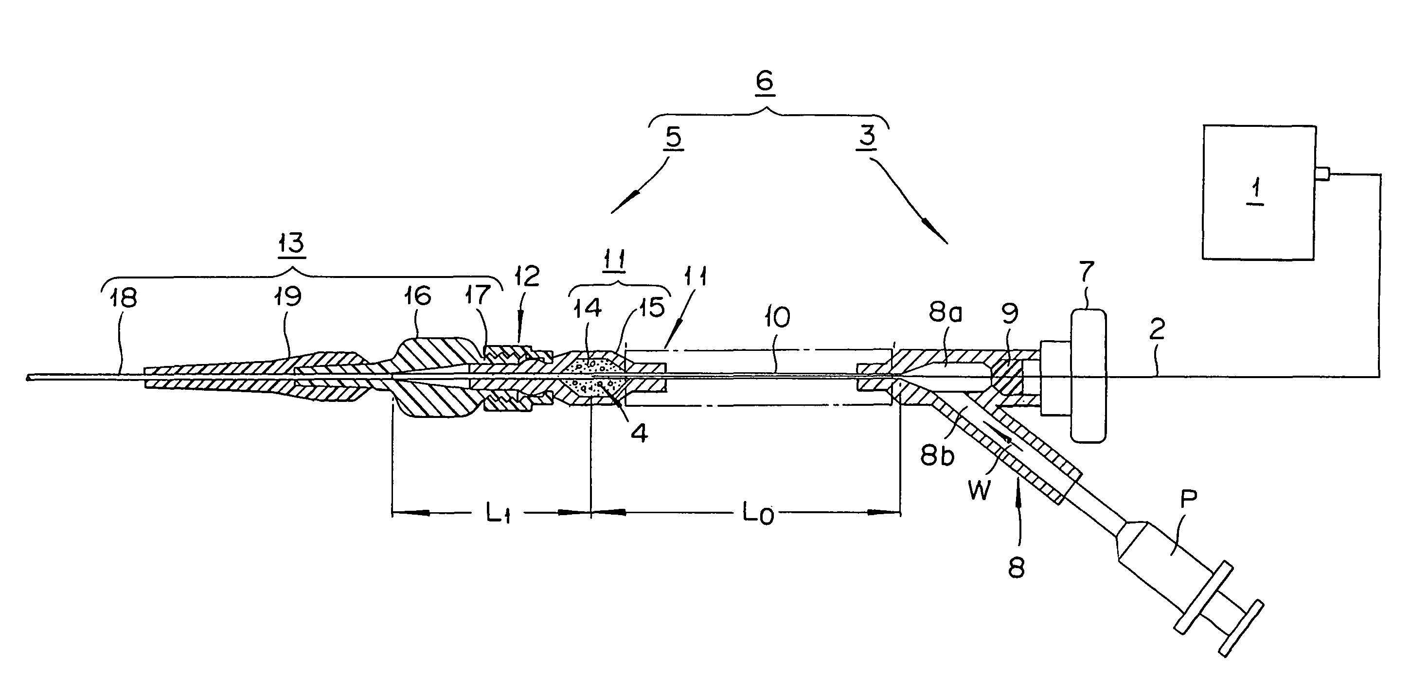
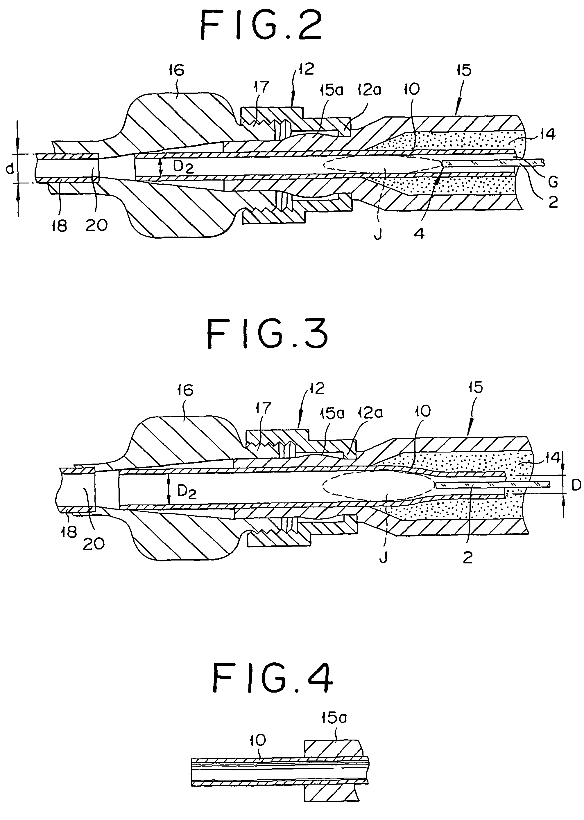
[0043]In FIG. 1, the laser induced liquid jet stream device of this embodiment generally includes a laser oscillator 1, an optical fiber 2 connected to the laser oscillator 1, and a main body 6. The main body 6 includes a base unit 3 for allowing the optical fiber 2 to penetrate through to hold it, and an operating unit 5 in which a laser irradiating part 4, namely a tip part of the optical fiber 2 extended from the base unit 3, is contained inside of a jet generating tube unit 10.

[0044]Since it is preferable to use a long jet generating tube unit 10 to make it possible to materialize a high power laser irradiation, the base unit 3 and the operating unit 5 are made separate from one another. Since the laser generator 1 and the optical fiber 2 are publicly known, a detail description of such features is not provided.

[0045]A detailed description of the other aspects of the device follows. First, in the base unit 3 of the main body 6, a so-called “Y-connector”8 is screwed on to the dis...

second embodiment

[0086]FIG. 12 shows the second embodiment of the invention. Those members common to those in FIG. 1 are labeled in the similar manner to omit the description.

[0087]Although different flow passages are used for the cooling liquid intended for cooling the jet generating tube unit 10 and the liquid to be introduced into the inside of the jet generating tube unit 10 in the first variation of the previous embodiment, the cooling liquid is introduced into the jet generating tube unit 10 in this embodiment.

[0088]As can be seen in FIG. 12, the duct 30 is constructed in such a way that the inlet 31 is located at a position corresponding with the laser irradiation part 4, the outlet 32 is located to open upward on the proximal side of the duct 30, and a guide tube 33 provided at the outlet 32 guides the liquid W that flows out to the inside of the jet generating tube unit 10.

[0089]With such an arrangement, since the cooling liquid is guided directly to the jet generating tube unit 10, the ope...

third embodiment

[0108]FIG. 19 shows a key area of a third embodiment. Those members common to those in the previously mentioned drawings are labeled in the similar manner to omit the description.

[0109]The aforementioned jet generating tube unit 10 is constructed in such a way that it prevents laser beams from passing, but the jet generating tube unit 10 of this embodiment is constructed in such a way as to allow laser beams to pass through as the photo / thermal effect of laser beams are shut off by a shut-off means provided separately.

[0110]If the jet generating tube unit 10 is transparent (laser beam permeable), the jet generating tube unit 10 tends to absorb little laser beams, thus receiving little photo / thermal effect, so that it is possible to minimize the degeneration and deterioration of the jet generating tube unit 10 and to prolong its life.

[0111]While such a jet generating tube unit 10 can be made of: fluorocarbon resins (tetrafluoroethylene-perfluoroalkylvinylether copolymer (PFA), polyte...


PUM


Abstract

A laser induced liquid jet generating device comprising: a main body 6 adapted to be filled with a specified laser beam absorbing liquid and configured such that it can contain a laser irradiating part 4 of an optical fiber from which laser beams are emitted to generate jet streams J of said liquid W by irradiating said liquid W with laser beams, with said jet streams J ejected from said main body 6 to the outside; said main body 6 comprising: a catheter mounting unit mounted integrally or in a removable manner on a catheter member 13 into which said jet stream J is introduced; a jet generating tube unit 10 in which said laser irradiation part 4 is adapted to be positioned; and a heat transfer inhibition means 11 for inhibiting thermal effect due to laser beams irradiated by said laser irradiating part 4 from being transferred outside through said jet generating tube unit 10. Thus, it provides a laser induced liquid jet generating device that is safe for both the operator and the patient as it can apply irradiation of powerful laser beams for a long period of time without the catheter being thermally affected by the laser beams.

Description

[0001]This application is based on Patent Application No. 2005-95138 filed on Mar. 29, 2005 in Japan and Patent Application No. 2006-031214 filed on Feb. 8, 2006 in Japan, the content of which is hereby incorporated by reference.BACKGROUND DISCUSSION[0002]1. Field of the Invention[0003]The present invention relates to a laser induced liquid jet generating device that generates a jet stream by irradiating liquid with a laser beam.[0004]2. Description of the Related Art[0005]As a way of treating thrombosis, i.e., a condition in which human blood vessels are obstructed, a treatment method of physically pulverizing matter causing thrombosis with a liquid jet stream has been discovered in recent years. This treatment method is highly appreciated as a very promising treatment method for thrombosis as it is not necessary to administer thrombolytic agents in large quantities which can cause serious adverse effects such as bleeding. Also an earlier resumption of blood flow is possible compar...

Claims


Application Information

Patent Timeline
Patent Type & Authority Patents(United States)
IPC IPC(8): A61B17/00
CPCA61B17/32037A61B18/20A61B17/3203A61B18/245A61B2017/00778A61B2017/22067A61B2018/206A61B2217/005A61M1/0023A61M1/76
Inventor HAYAKAWA, KOICHIWATANABE, KOHEI
Owner MICHELIN RECH & TECH SA
Why Eureka
Try Eureka