Power supply device in a device for electrochemical treatment

a power supply device and electrochemical treatment technology, applied in contact devices, electrodialysis, refrigeration components, etc., can solve the problems of reducing the thickness of the metal layer on the material to be treated, repeated damage of the insulator layer, and inability to use the reject board in the subsequent etching step

Active Publication Date: 2010-10-19
ATOTECH DEUT GMBH
View PDF36 Cites 3 Cited by
  • Summary
  • Abstract
  • Description
  • Claims
  • Application Information

AI Technical Summary

Benefits of technology

[0036]Trials with an electrical supply unit in accordance with the invention have shown that, without using additional plastic seals in the vicinity of the material to be treated, the deposition of metal on the blank electrically conductive material was then only about 0.005 mm per pass on average, that is to say far lower than the 0.04 mm limit. No reduction of the metal layer on the material to be treated could be found due to the robber cathode effect described in the introduction.

Problems solved by technology

Specifically, in the immediate vicinity of the electrical feed, the undesired metal deposit on the electrical feed leads to a reduction in the thickness of the metal layer on the material to be treated.
For example when printed circuit boards are being coated, for which very uniform layers are important, this leads to unusable reject boards in a subsequent etching step.
Despite the elaborate processing and the use of high-quality special plastics such as Halar™, such insulator layers are repeatedly damaged by a sharpedged material to be treated, especially when automatic coating units are used for galvanising devices.
Often after only a short time, this metal can no longer be removed by inexpensive electrolytic demetallising because, with this method, the conducting connection to the usually relatively small-area points of damage is frequently broken before all the deposited metal can be dissolved.
All these working steps are elaborate and very expensive.
With a layer thickness beyond 0.1 mm per pass for this layer, interference with production is to be expected.
Another disadvantage with this embodiment is that, in the case of electrical feeds arranged as in FIG. 8, the masks cannot be moved together with the engaging movements of the electrical feeds.

Method used


Image

  • Power supply device in a device for electrochemical treatment
  • Power supply device in a device for electrochemical treatment
  • Power supply device in a device for electrochemical treatment

Examples


Embodiment Construction

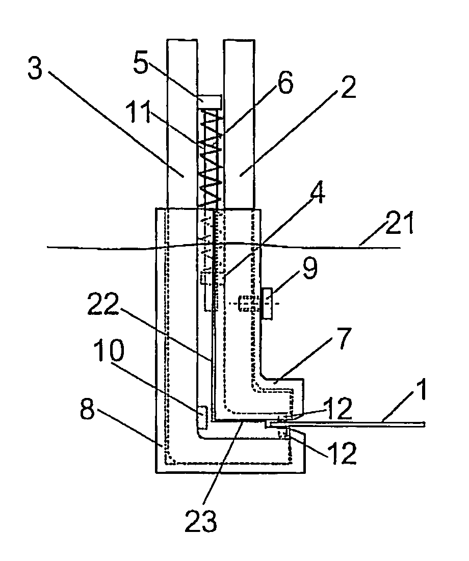
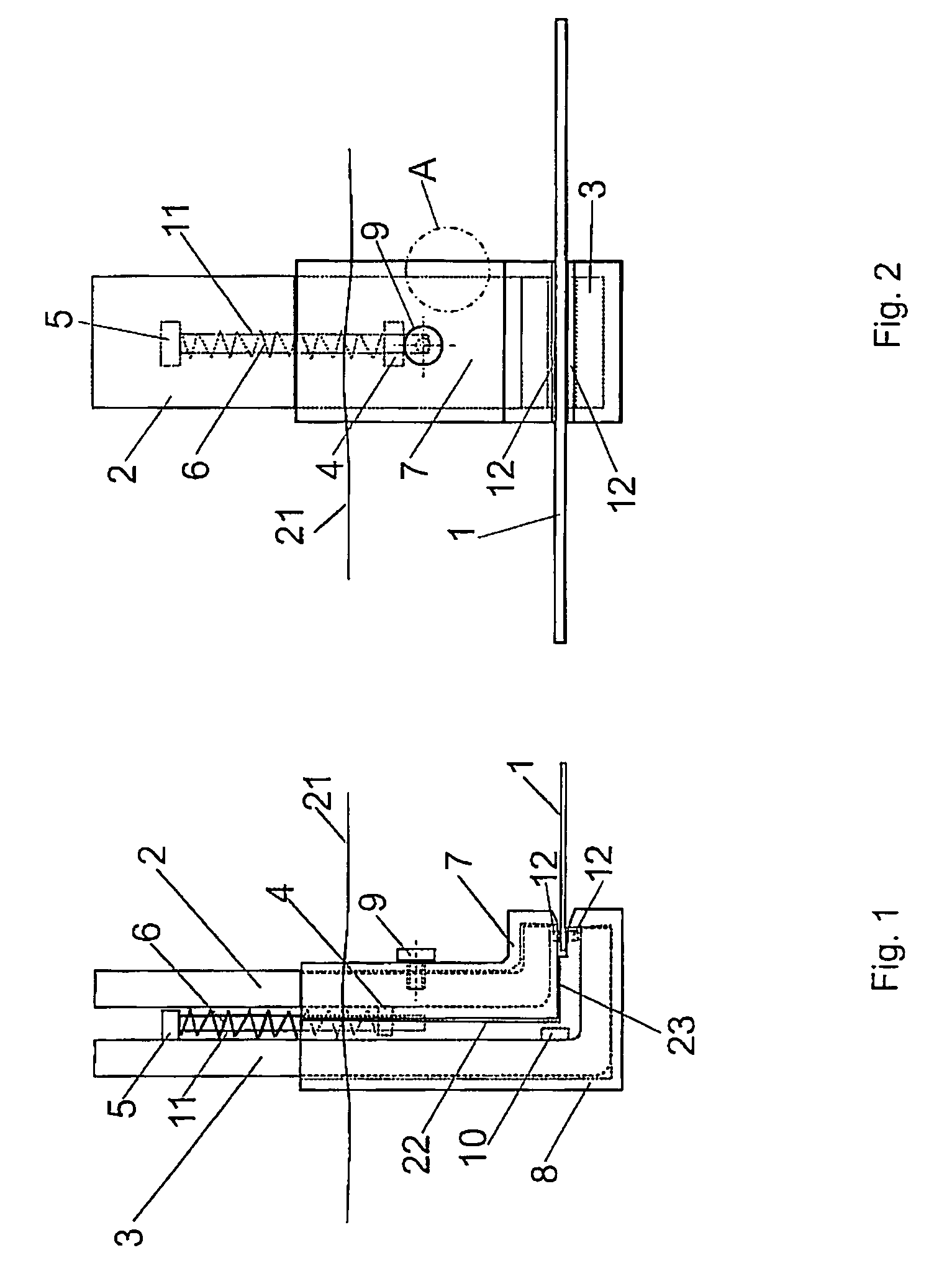
[0046]FIG. 1 represents an exemplary embodiment of an electrical supply unit in accordance with the invention, in the same view as in FIG. 8 which was described in the introduction. The same references are used for elements which correspond to each another. A material 1 to be treated is held, and electrical contact is made with it, by a clamp which is formed by an upper electrical feed or a clamp upper part 2 and a lower electrical feed or a clamp lower part 3, with the clamp upper part 2 and the clamp lower part 3 respectively consisting of a blank material with good conductivity. A guide block 4, in which a spring guide 11 is mounted so that it can move in the vertical direction in a bore, is rigidly fastened to the clamp upper part 2. The clamp lower part 3 has a rigidly fastened spring block 5, in which the spring guide 11 is firmly engaged. Between the two blocks 4 and 5, a spring is arranged on the spring guide 11 and presses the clamp upper part 2 against the clamp lower part...


PUM

PropertyMeasurementUnit
thicknessaaaaaaaaaa
thicknessaaaaaaaaaa
thicknessaaaaaaaaaa

Abstract

In order for electrical feeds (2, 3) of an electrical supply unit for material (1) to be treated, in a device for the electrochemical treatment thereof, to be protected against metal deposition, it is proposed that at least one electrically insulating shell (7, 8) should be provided, which encloses the at least one electrical feed (2, 3), over a particular length starting from contact means (12) for making contact with the material to be treated, so that no metal deposit of more than 0.04 mm is formed on the blank parts of the electrical feed when the electrical feed (2, 3) is immersed up to this particular length in a liquid during the electrochemical treatment of the material (1) to be treated.

Description

[0001]This application is a National Stage application of International Application No. PCT / EP2004 / 009272, filed Aug. 18, 2004, which claims priority to German Application No. DE 103 40 888.6, filed Sep. 4, 2003.BACKGROUND OF THE INVENTION[0002]1. Field of the Invention[0003]The present invention relates to an electrical supply unit for material to be treated in a device for the electrochemical treatment thereof, especially in galvanising or etching systems.[0004]1. Description of the Related Art[0005]For the electrolytic application of a conductive layer (galvanising), a material to be treated is connected via electrical feeds and fastening means to a negative pole of a direct-current source. An opposite electrode, in this case the anode, is accordingly connected electrically conductively to a positive pole of the direct-current source. Both the anode and the material to be treated lie in an electrolyte which contains positively charged ions of the material to be applied. Because o...

Claims


Application Information

Patent Timeline
Patent Type & Authority Patents(United States)
IPC IPC(8): C25C7/00B23H3/00C25B9/00C25D17/06
CPCC25D17/005C25D17/06B33Y80/00
Inventor SCHELLER, BRITTABREHM, KLAUSLORENZ, OLAF
Owner ATOTECH DEUT GMBH
Why Eureka
Try Eureka