Integration of hydrogen and power generation using pressure swing reforming

a technology of hydrogen and power generation, applied in the direction of hydrogen separation using solid contact, petrochemical industry, chemistry apparatus and processes, etc., can solve the problems of 20% or more fuel penalty, high cost and inefficiency of cosub>2 /sub>capture technology, etc., to reduce the volume flow rate and power requirement of the blower. , the effect of improving process efficiency

Active Publication Date: 2010-10-19
EXXON RES & ENG CO
View PDF13 Cites 72 Cited by
  • Summary
  • Abstract
  • Description
  • Claims
  • Application Information

AI Technical Summary

Benefits of technology

[0042]In FIG. 2 no provision for heat exchange or conditioning is shown. Indeed, an advantage of the present invention is that pressure swing reforming syngas effluent (129) conditions can be tuned to require no conditioning prior to introduction into the shift reactor (130). However, it is understood that conditioning as is known in the art may be applied to these streams. For example, heat exchange may be applied to adjust temperatures. The separation step (132) generally requires synthesis gas at conditions different from the exit conditions of the shift step (130).
[0043]The reforming inlet stream is composed of hydrocarbon (112) and steam (114). These streams may be preheated to any level that is economically achievable with heat available around the process. Typically, the steam (114) will be available at about the boiling temperature that corresponds to the pressure of reformer operation, typically 200° C. to 300° C. Waste heat is typically available that can heat the reforming feeds to temperatures in the range of 200° C. to 400° C. Increasing the preheat will improve process efficiency at a cost of added heat exchange. This tradeoff is well known in the art, and can be optimized by one skilled in the art for any given situation of capital and energy cost. The incoming reforming feed temperature sets a lower limit on the temperature of the outgoing fluegas (137). However, the temperature of the outgoing fluegas is also strongly influenced by the temperature that remains in the reforming section of the bed (1) at the end of the reforming stage. That remaining temperature is strongly influenced by the kinetics of reforming, the pressure, and space velocity. Under the conditions described herein, the flue gas (137) will be at temperatures in the range of about 400° C. to about 600° C.
[0044]The regeneration stage (102) of the pressure swing reformer (128) is carried out by introducing hydrogen-containing gas (135) and an oxygen containing gas (136), e.g., air, into the reformer (128) for combustion therein. The oxygen-containing gas (136) used for regeneration is obtained as air that is extracted from a gas turbine (140).
[0045]As stated previously, at least a portion of the separated hydrogen (133) is provided as fuel (138) for combustion in a gas turbine. A typical gas turbine is diagrammatically shown in FIGS. 2 and 3 as comprising a compressor (143) and gas expander (also sometimes referred to as a turbine) (144) on common shaft (149), and a combustor (147). Ambient air (142) is compressed in the compressor (143) whereupon it flows as hot compressed air (146) into a combustion step (147) in which fuel (138) is burned to create a very hot, high pressure fluegas (148) that is expanded in gas expander (144) to an ambient-pressure fluegas (141). It is understood that the combustor step typically divides the air into an “oxidant” fraction that is used in combustion and a “diluent” fraction that is used cool the combustor and combustion products to acceptable turbine-inlet temperature. The expander (144) releases more power to shaft (149) than is required by the compressor (143), and the remaining power is converted by generator (150) into electricity, or used as mechanical work, for example to drive other compressors. In a combined cycle gas turbine system, the ambient-pressure fluegas (141) is further cooled in a steam generating system (139) to yield pressurized steam (151) and cooled fluegas (153). The steam (151) product in then expanded in a steam turbine to produce additional power. It is known in the art that a fraction of the hot compressed air (145) can be removed from the gas turbine and used in an external process, without upsetting the gas turbine operation. Typically, when air is extracted, replacement gas is supplied to the expander (144) to preserve the power output of the gas turbine.
[0046]In the present invention, the oxygen-containing gas (136) used for regeneration (102) is obtained as air that is taken as a fraction of the hot compressed air (145) that has been compressed in the gas turbine (140). The remaining hot compressed air (146) is sent to the combustor (147). Fluegas (137) from the pressure swing reforming regeneration stage (102) is returned to the gas turbine combustor step as oxidant and / or diluent.
[0047]When the regeneration stage (102) of pressure swing reforming is coupled to a gas turbine, as described in FIG. 2, the temperature and pressure of the regeneration feed (136) take on the characteristics of the gas turbine's hot compressed air (145). Typically the regeneration feed will be at a temperature in the range of about 200° C. to 650° C. and preferably at 300° C. to 500° C. The regeneration stage will be operated at pressures in the range of about 5 to about 30 bar, and preferably in the range of about 10 to about 20 bar.

Problems solved by technology

Present technologies known in the art for CO2 capture in power generation are both expensive and inefficient.
Combining conventional steam reforming, partial oxidation or autothermal reforming with gas turbine power generation can result in a fuel penalty of 20% or more.

Method used


Image

  • Integration of hydrogen and power generation using pressure swing reforming
  • Integration of hydrogen and power generation using pressure swing reforming
  • Integration of hydrogen and power generation using pressure swing reforming

Examples


example 1

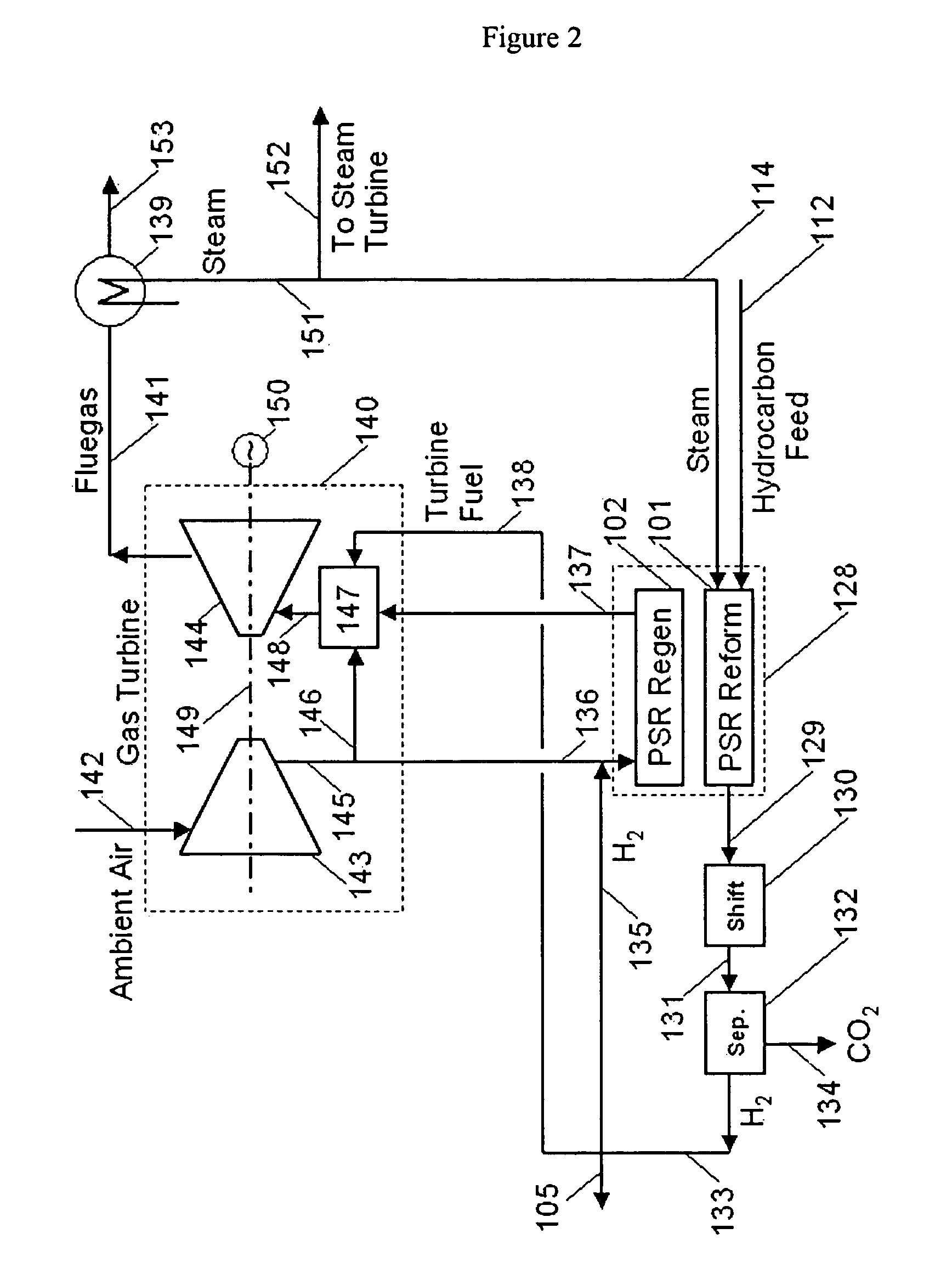
[0055]To further illustrate the invention key streams of the calculated heat and material balance for the embodiment shown in FIG. 2 is given in Table 1. This pressure swing reformer system is operated as two cylindrical reactors, with internal dimensions of 11 ft (3.4M) diameter and 4 ft (1.2M) length. The reactors are positioned with cylindrical axis in a vertical orientation, and reforming is carried out as up-flow; regeneration as down-flow. The packing is composed of 400 cell / in2 (62 cell / cm2) honeycomb monolith having a bulk density of 50 lb / ft3 (0.8 g / cc). The bottom 70% of the packing includes reforming catalyst. Overall cycle length is 30 seconds; 15 s for the regeneration stage and 15 seconds for the reforming stage. A brief steam purge is included at the end of the reforming stage.

[0056]The reforming stage (101) is fed with methane (112) at the rate of 1760 kgmoles / hr, accompanied by steam (114) at a rate of 4494 kgmoles / hr, representing a reforming C1GHSV of 3,600 hr−1. ...

example 2

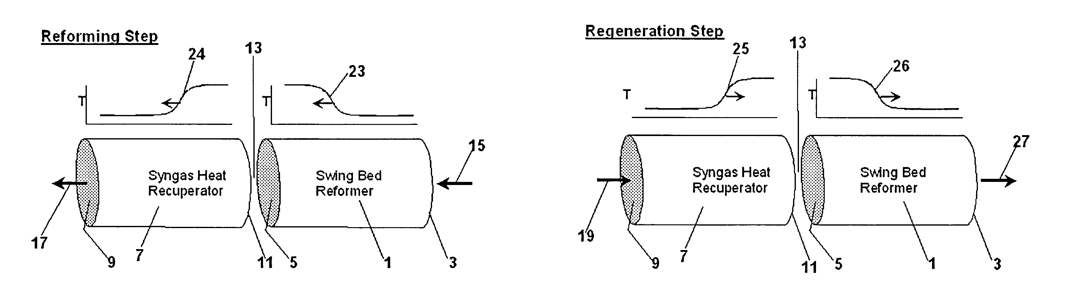
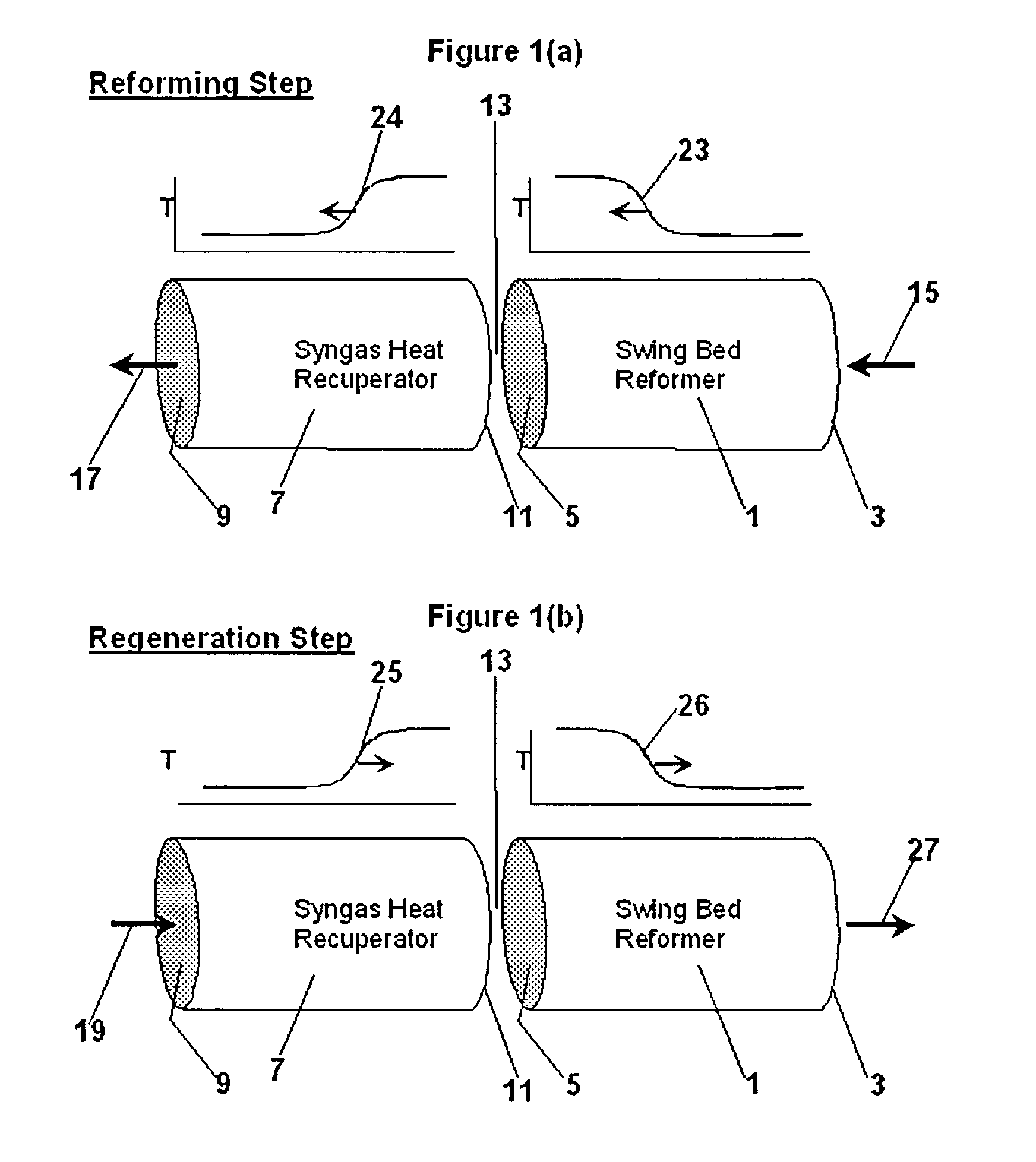
[0061]To further illustrate the invention, key streams of a calculated heat and material balance for the embodiment shown in FIG. 2 is given in Table 2. In this example, the pressure swing reformer operated at lower reforming efficiency by increasing the reforming space velocity and increasing regeneration flow rate relative to reform. Increasing space velocity at constant cycle time has the effect of increasing the amount of heat that is stored in the bed in each cycle. This results in a reform-bed temperature profile (26 of FIG. 1b) that must be closer to the bed outlet (3 of FIG. 1b) at the end of regeneration, and consequently a higher fluegas outlet (137) temperature. The increase in regeneration rate has the effect of driving the temperature profile (26 of FIG. 1b) even farther across the bed, resulting in yet higher regeneration fluegas (137) temperature. The reformer is less efficient because more of the heat value of the regeneration fuel (135) is expended to heat the flueg...

example 3

[0067]To further illustrate the invention, key streams of a calculated heat and material balance for the embodiment shown in FIG. 3 is given in Table 3. In this example, the pressure swing reformer operated as two cylindrical reactors, with internal dimensions of 11 ft (3.4M) diameter and 4 ft (1.2M) length. The reactor configuration, packing and cycle are the same as described with respect to Example 1.

[0068]The reforming stage (101) is fed with methane (112) at the rate of 1838 kgmoles / hr, accompanied by steam (114) at a rate of 4693 kgmoles / hr, representing a reforming C1GHSV of 3,600 hr−1. Syngas (129) is produced at rates shown in Table 3, is cooled to 280° C. by heat exchange to produce steam, and is converted in an adiabatic, high temperature shift reactor (130) to yield shifted product (131). Separation is accomplished using a high-temperature, palladium-based membrane system (170) operating at about 385° C. with internal water gas shift activity. Compositions, flows and con...


PUM

PropertyMeasurementUnit
pressureaaaaaaaaaa
pressureaaaaaaaaaa
pressuresaaaaaaaaaa

Abstract

The invention provides a method for generating power with a gas turbine which utilizes pressure swing reforming under conditions that facilitate CO2 capture. First a synthesis gas stream at a first pressure is produced in a pressure swing reformer. Next the synthesis gas stream is subjected to a high temperature water gas shift process to produce a CO2 containing hydrogen enriched stream from which hydrogen and CO2 each are separated. The separated hydrogen in turn is combusted with air to produce a gas turbine and the separated CO2 is easily sequestered.

Description

[0001]This application is a Continuation-in-Part of U.S. patent application Ser. No. 10 / 771,919 filed Feb. 4, 2004 which is a Continuation-in-Part of Non-Provisional application Ser. No. 10 / 756,652 filed Jan. 13, 2004 now abandoned which is based on Provisional Application No. 60 / 450,903 filed Feb. 28, 2003.FIELD OF INVENTION[0002]The present invention relates to a method for generating power with a gas turbine which utilizes pressure swing reforming under conditions that facilitate CO2 capture.BACKGROUND OF INVENTION[0003]Pressure swing reforming is a highly efficient and highly productive process for stream reforming hydrocarbons in a cyclic, packed-bed operation to produce synthesis gas.[0004]In this process, the reforming stage involves preheating a first zone to a temperature in the range of about 700° C. to 2000° C. and then introducing a 20° C. to 600° C. hydrocarbon-containing feed, along with steam and optionally CO2 to the inlet of the first zone. Upon introduction of the ...

Claims


Application Information

Patent Timeline
Patent Type & Authority Patents(United States)
IPC IPC(8): C01B3/02C01B3/24C01B3/26C01B3/38C01B3/46
CPCC01B3/38C01B3/48C01B3/50C01B3/56C01B3/46Y02P30/30C01B2203/00C01B2203/0233C01B2203/0283C01B2203/0288C01B2203/0405C01B2203/0415C01B2203/0425C01B2203/043C01B2203/046C01B2203/0475C01B2203/0805C01B2203/0811C01B2203/0872C01B2203/0883C01B2203/1041C01B2203/1047C01B2203/1058C01B2203/1064C01B2203/1076C01B2203/1082C01B2203/1235C01B2203/1241C01B2203/1247C01B2203/1288C01B2203/1294C01B2203/1619C01B2203/1623C01B2203/1676C01B2203/168C01B2203/84Y02P30/00C01B3/24C01B3/26
Inventor HERSHKOWITZ, FRANKDECKMAN, HARRY W.
Owner EXXON RES & ENG CO
Why Eureka
Try Eureka