Method for post-injection lamination to add a functional film to an optical lens

a functional film and lens technology, applied in the direction of coatings, applications, instruments, etc., can solve the problems of degrading or partially destroying the functionality built into the film, requiring resources and energy, and cleaning and dip coating process requires a large investment of space, so as to achieve the effect of combining a functional film and a lens

Active Publication Date: 2010-10-26
ESSILOR INT CIE GEN DOPTIQUE
View PDF17 Cites 36 Cited by
  • Summary
  • Abstract
  • Description
  • Claims
  • Application Information

AI Technical Summary

Benefits of technology

[0008]It is an object of the present invention to provide an in-mold lamination system that easily combines a functional film with a lens.
[0011]It is an additional object to broaden the range of film materials that can laminated.
[0013]In a first step of the method, molten thermoplastic resin is injected into a lens-forming cavity held closed under a primary clamp force. The mold is opened at a time when the lens is rigid enough to retain its shape and separate from one of the inserts. An unpressurized full metered charge of curable glue is deposited onto the center of the lens. Next a functional film is introduced between the glue and the separated insert. The mold is then closed to a secondary clamp force less than or equal to the primary clamp force to thinly spread the glue between the film and lens so that it cures with the heat transferred from the mold and the diminishing residual heat of the lens.

Problems solved by technology

The cleaning and dip-coating process requires a large investment of space, resources and energy.
A serious drawback of FIM, is the requirement that the facing layer of the film be the same or compatible with the lens resin, to obtain a fusion between the material of the facing layer of the film and the injected resin.
Another drawback of FIM, is related to the high temperature required to obtain melted resin which could degrade or partially destroy the functionality built into the film.

Method used


Image

  • Method for post-injection lamination to add a functional film to an optical lens
  • Method for post-injection lamination to add a functional film to an optical lens
  • Method for post-injection lamination to add a functional film to an optical lens

Examples


example 1

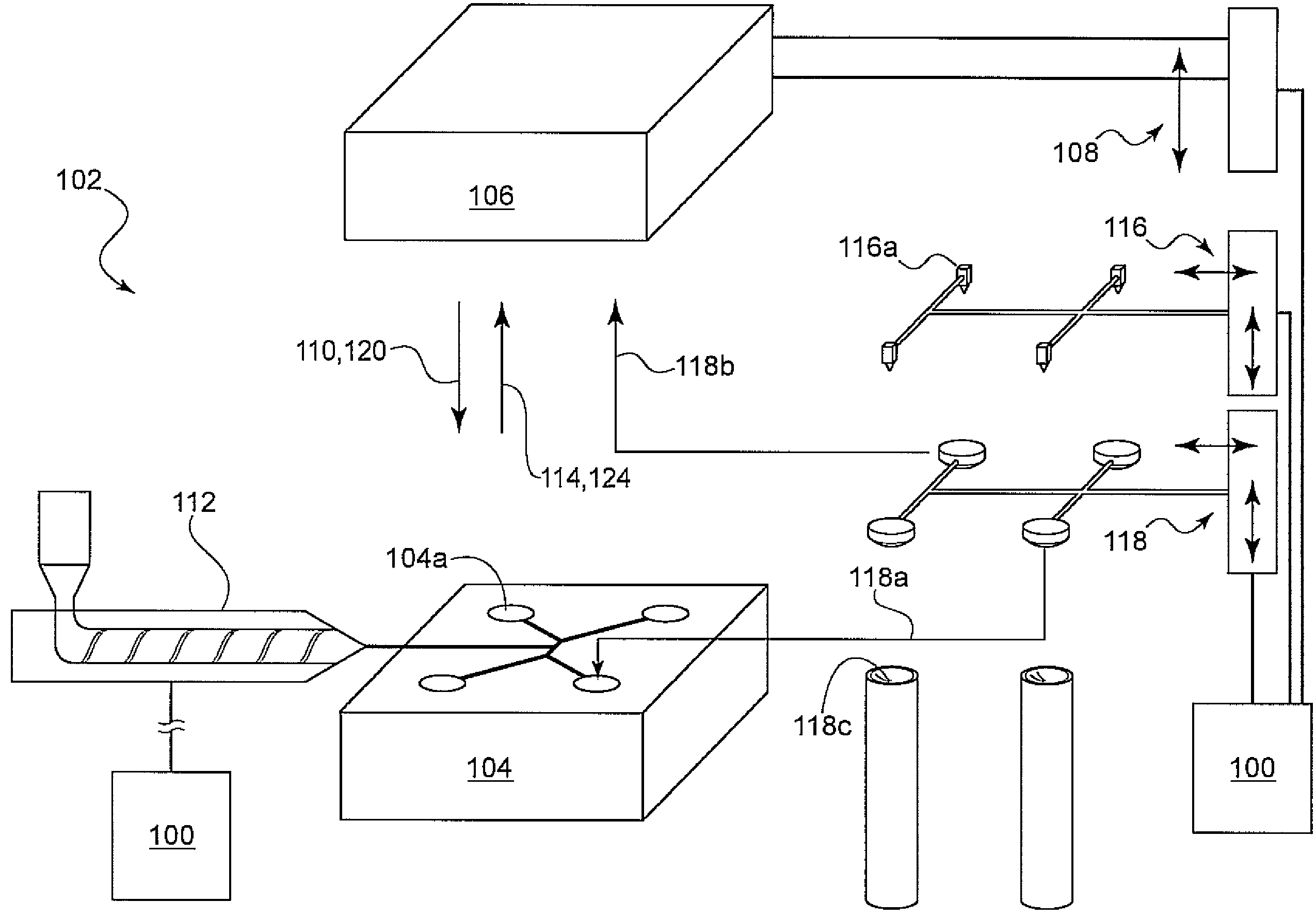
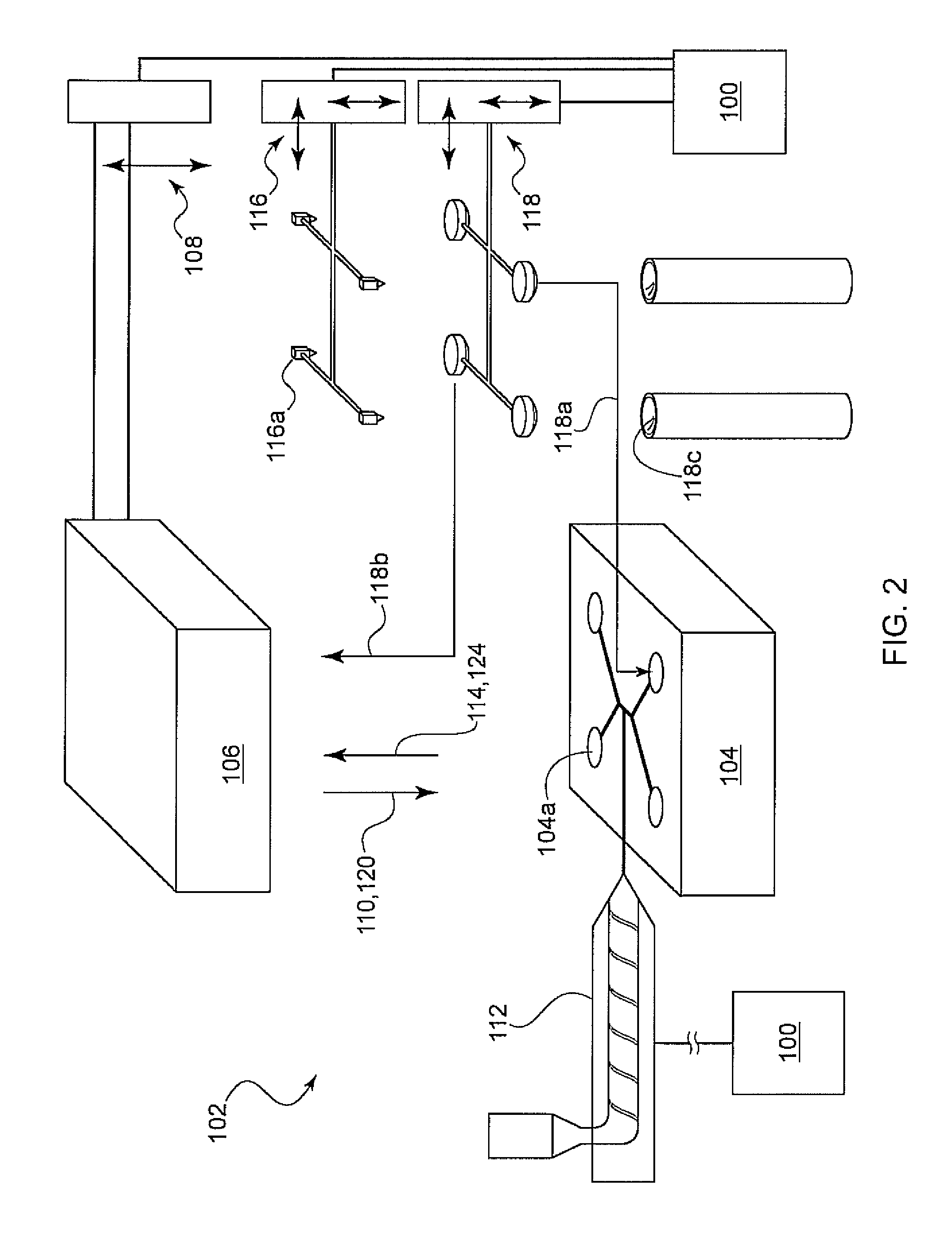
[0028]Post injection in-mold lamination experiments were conducted using an Engel ES700H 150 US ton vertical injection molding machine equipped with a 2-cavity side-entry mold. Polarizing films having a PVA (polyvinyl acetate) polarizing element sandwiched between two polycarbonate (PC) sheets were laminated to polycarbonate (PC) lenses using acrylate based glue.

[0029]The experiments were conducted according to the steps mentioned above. First, two 6.50-base SFSV (semi-finished single vision) PC lenses, 76 mm in diameter and 9 mm in thickness, were injected using the following process parameters. The melt temperature Tm was 510 degrees F. in the screw injector. The mold temperature was 260 degrees F. The shot size was 2.50 inches, and the injection speed was 0.1 inch / s. The packing pressure had a machine specific reading of 800 psi, which was estimated to deliver an actual packing pressure of 9,000 psi onto the molten resin. The cooling time was 4 minutes.

[0030]At the end of cooling...


PUM

PropertyMeasurementUnit
pressureaaaaaaaaaa
wait timeaaaaaaaaaa
diameteraaaaaaaaaa

Abstract

A method for laminating a functional film on to a thermoplastic injection molded lens. A thermally curable glue is deposited on the lens while it is still in the mold. A functional film is introduced and the mold is closed again. The heat from the mold and the clamping pressure thermoform the film and cure the glue, in a lamination process. A functionally enhanced lens having a film intimately laminated on to one side.

Description

BACKGROUND OF THE INVENTION[0001]1. Field of the Invention[0002]The invention relates to laminating a functional film onto an injection molded ophthalmic lens using the clamp pressure, mold temperature, and residual resin heat to cure a thermally curable glue, preferably an acrylate based glue, to facilitate the bonding between the film and the lens.[0003]2. The Prior Art[0004]In the manufacture of plastic lenses, the injection molded lens is removed from the mold for further processing to integrate specific functions such as anti-reflective, photochromic, or anti-scratch to the lens. Typically the lenses are cleaned and dip-coated with a tint coating, photochromic coating, anti-reflective coating, hard coating or other protective coating layers. The cleaning and dip-coating process requires a large investment of space, resources and energy.[0005]Other approaches involve laminating a single or multi-layer functional film onto the lens. One technique known as film insert molding (FIM...

Claims


Application Information

Patent Timeline
Patent Type & Authority Patents(United States)
IPC IPC(8): B29D11/00G02B3/00G02B5/30G02B5/32
CPCB29D11/0073B29C69/007B29C45/0053B29C37/0028B29C2037/0042B29C2045/0079B29C43/18B29L2011/0016
Inventor CHIU, HAO-WENLOCKWOOD, MATTHEW JAMES
Owner ESSILOR INT CIE GEN DOPTIQUE
Why Eureka
Try Eureka