Eureka AIR delivers breakthrough ideas for toughest innovation challenges, trusted by R&D personnel around the world.

Low impedance column multiplexer circuit and method

a multiplexer circuit and low impedance technology, applied in the direction of power conversion systems, dc-dc conversion, digital storage, etc., can solve the problem achieve the effect of fast read speed, low impedance, and good sense of differential margins

Active Publication Date: 2010-10-26
LONGITUDE FLASH MEMORY SOLUTIONS LTD
View PDF46 Cites 14 Cited by
  • Summary
  • Abstract
  • Description
  • Claims
  • Application Information

AI Technical Summary

Benefits of technology

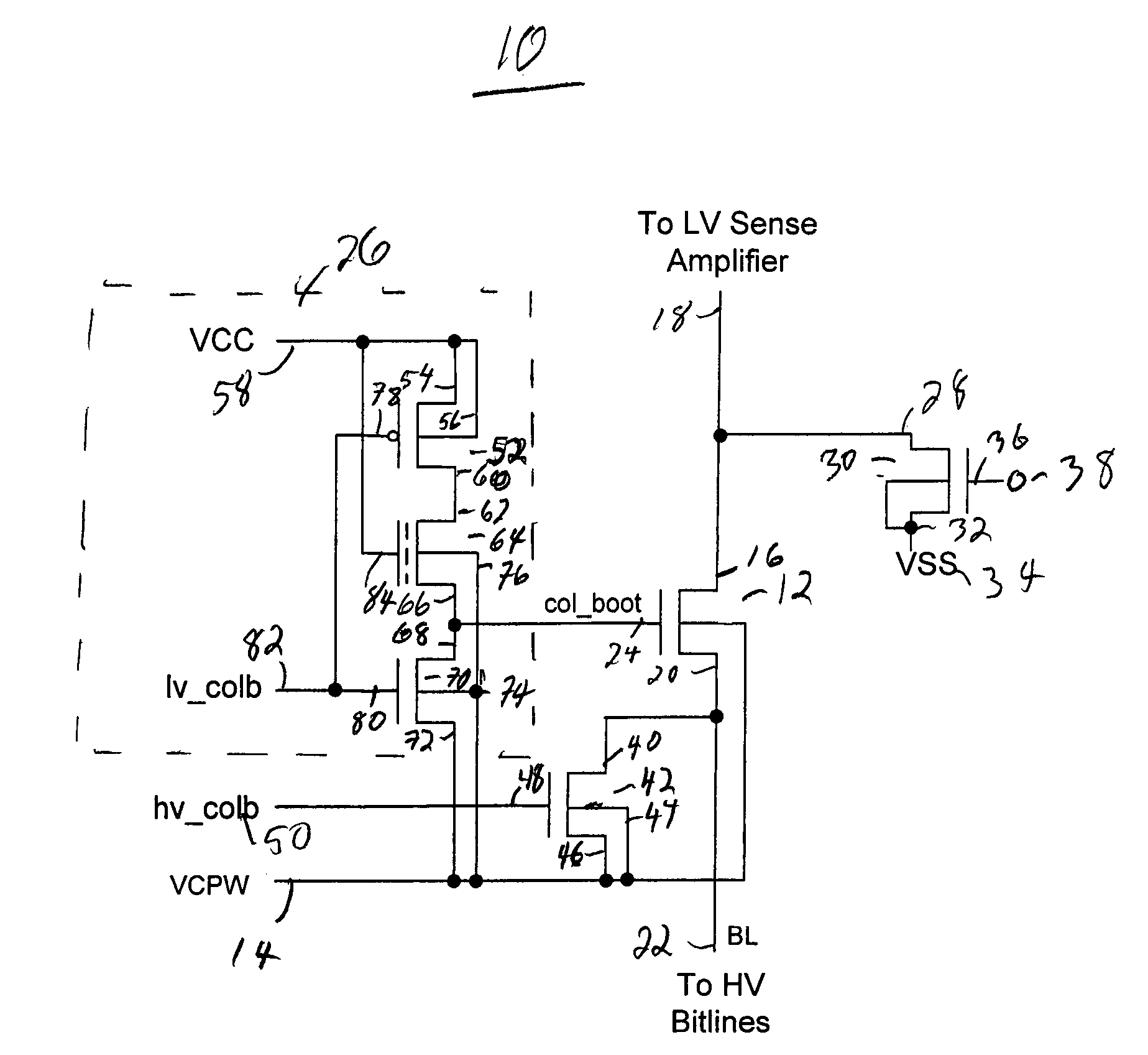
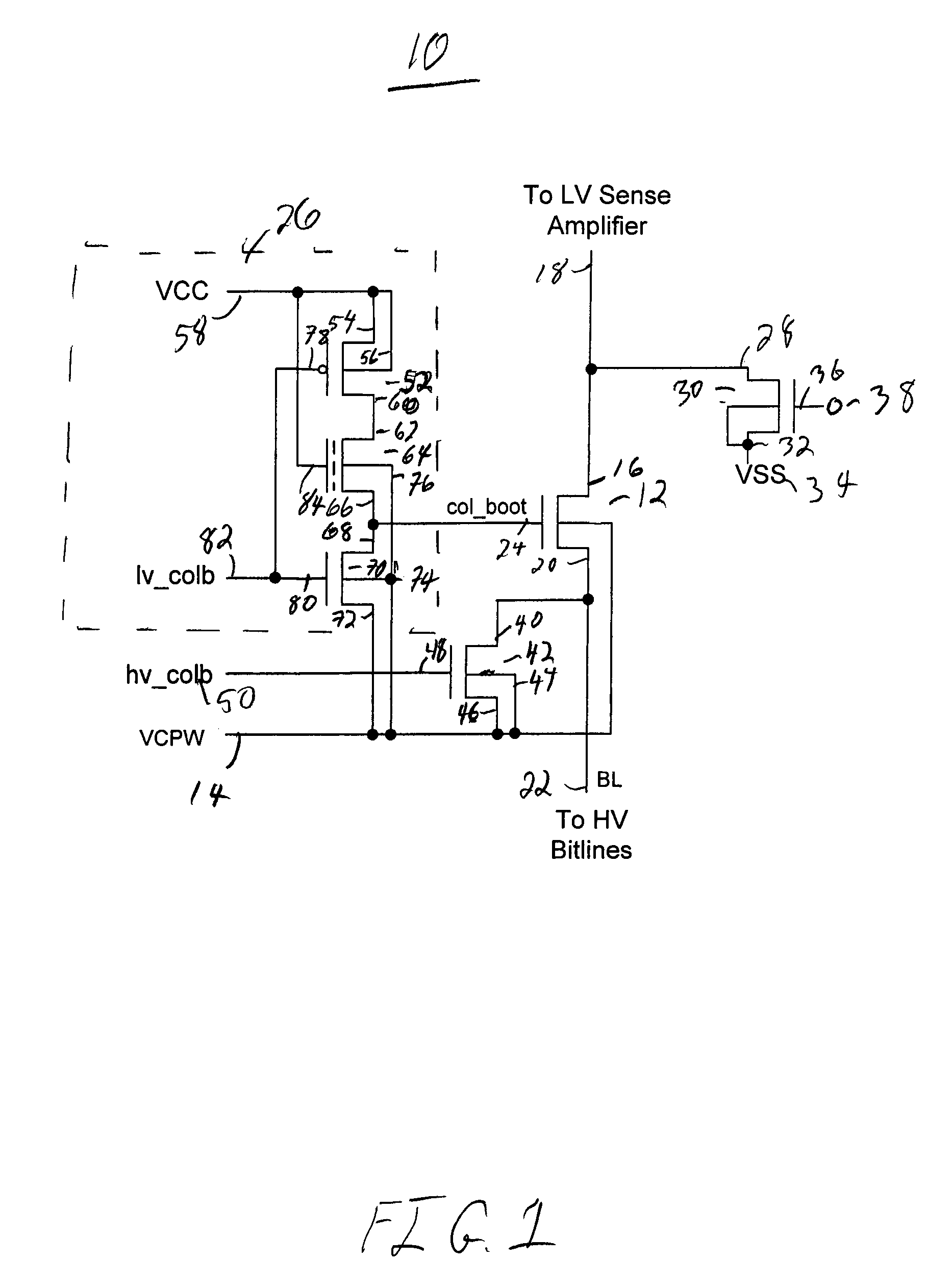
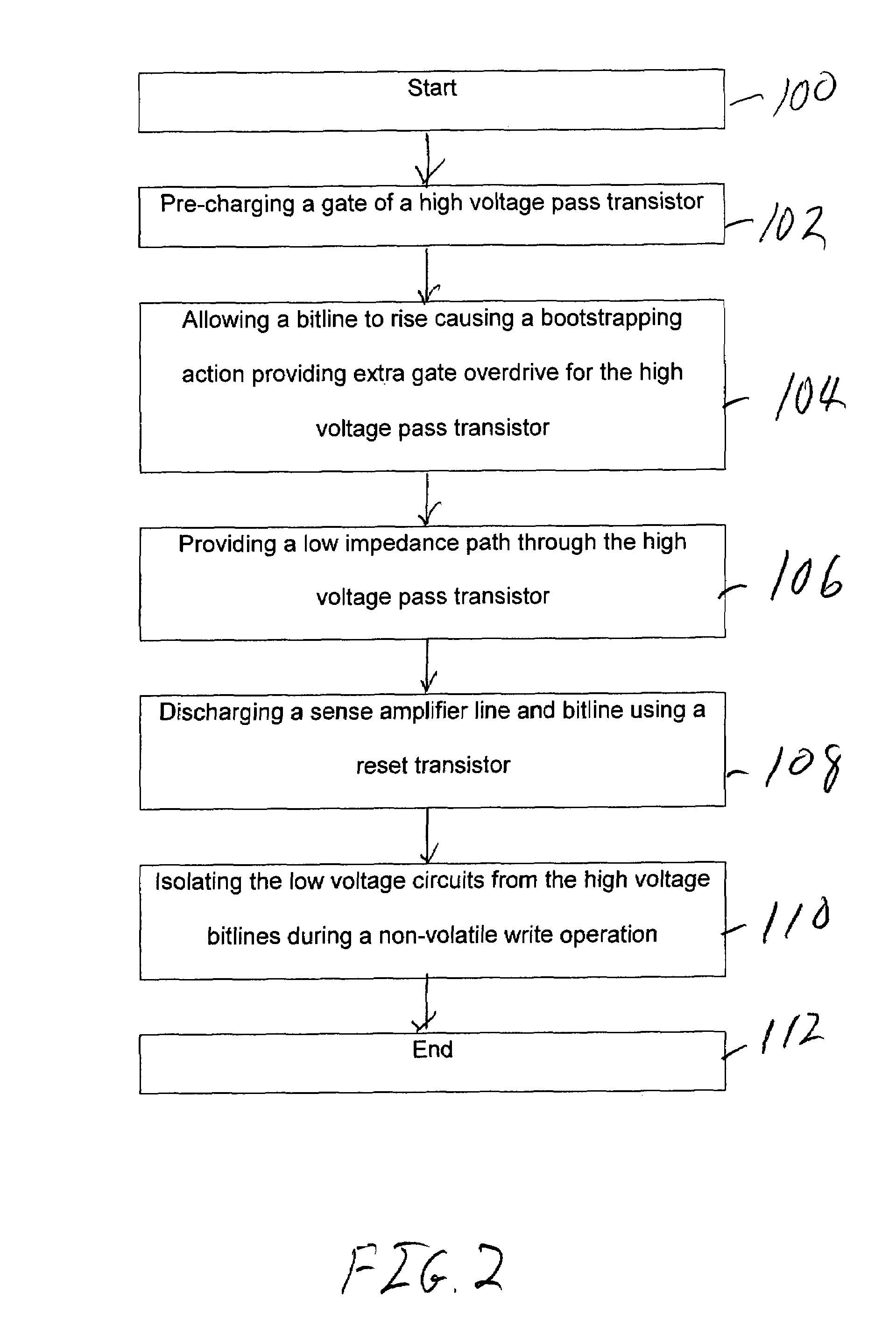
[0007]The present invention has a bootstrapped high voltage pass gate transistor that couples the low voltage sense amplifier to the bitlines. Since the pass gate transistor is bootstrapped its gate floats to the high voltage of the power supply (VCC) plus a delta voltage. This overdrives the pass gate transistor and allows it to pass signals between the sense amplifier and the bitlines with low impedance. This results in good sense differential margins and fast read speeds. The circuit has a pass gate control circuit that places a negative high voltage signal on the gate of the pass gate during non-volatile write operations. This causes the pass gate to isolate the low voltage circuits from the high voltage circuits during this operation. Finally, the circuit is smaller than earlier column multiplexer circuits, because the headroom and voltage drop issues across the multiplexer are not fixed by increasing the area of the pass devices, but it is fixed by using the bootstrapping effect, and the devices added to create the bootstrapping effect can be minimum-sized devices.

Problems solved by technology

This results in good sense differential margins and fast read speeds.

Method used


Image

  • Low impedance column multiplexer circuit and method
  • Low impedance column multiplexer circuit and method
  • Low impedance column multiplexer circuit and method

Examples


Embodiment Construction

[0010]The present invention includes a bootstrapped high voltage pass gate transistor that couples the low voltage sense amplifier to the bitlines. Since the pass gate transistor is bootstrapped, its gate floats to the high voltage of the power supply (VCC) plus a delta voltage. This overdrives the pass gate transistor and allows it to pass signals between the sense amplifier and the bitlines with low impedance. This results in good sense differential margins and fast read speeds.

[0011]FIG. 1 is a circuit diagram of a low impedance column multiplexer circuit 10 in accordance with one embodiment of the invention. The circuit 10 includes a high voltage pass gate transistor 12. Note as used herein “high voltage” device means a thick oxide device, and “low voltage” device means a thin oxide device. Naturally these terms are relative, but these are the terms used by those skilled in the art to describe devices that have different threshold and operating voltages, and, therefore, would be...


PUM


Abstract

The invention has a bootstrapped high voltage pass gate transistor that couples the low voltage sense amplifier to the bitlines. Since the pass gate transistor is bootstrapped its gate floats to the high voltage of the power supply (VCC) plus a delta voltage. This overdrives the pass gate transistor and allows it to pass signals between the sense amplifier and the bitlines with low impedance. This results in good sense differential margins and fast read speeds. The circuit has a pass gate control circuit that places a negative high voltage signal on the gate of the pass gate during non-volatile write operations. This causes the pass gate to isolate the low voltage circuit from the high voltage circuits during this operation. Finally, the circuit is smaller than earlier column multiplexer circuits.

Description

RELATED APPLICATIONS[0001]Not applicableSTATEMENT REGARDING FEDERALLY SPONSORED RESEARCH[0002]Not ApplicableTHE NAMES OF THE PARTIES TO A JOINT RESEARCH AGREEMENT[0003]Not applicableREFERENCE TO A SEQUENCE LISTING, A TABLE, OR A COMPUTER PROGRAM LISTING[0004]Not applicableBACKGROUND OF THE INVENTION[0005]Non-volatile memories require a column multiplexer that can pass read bias voltages onto the bitlines for generating read currents through the memory cell. The column multiplexer is also required to withstand high voltages because the bitlines get high voltage biases during program / erase non-volatile operations. In state of the art technologies, the power supply is also very low (typically less than 1.8v). Since the pass device of the column multiplexer device has to withstand high voltages (around 10V), they have to be thick oxide devices which have high threshold voltages. Due to the high threshold voltages of the high voltage devices and limited power supply headroom, column mult...

Claims


Application Information

Patent Timeline
Patent Type & Authority Patents(United States)
IPC IPC(8): G11C8/00
CPCG11C7/1006G11C7/1012G11C7/18G11C2207/002
Inventor RAGHAVAN, VIJAY KUMAR SRINIVASAHIROSE, RYAN
Owner LONGITUDE FLASH MEMORY SOLUTIONS LTD
Why Eureka
Eureka Blog
Learn More