Connector for detonator, corresponding booster assembly, and method of use

a technology of connecting connectors and detonators, which is applied in the direction of electric fuzes, ammunition fuzes, lighting and heating apparatus, etc., can solve the problems of actuating the explosive material of the booster, affecting the initiation of the detonator's base charge, and causing more powerful shockwaves for rock fragmentation, so as to prevent the ingress of water and/or dirt

Inactive Publication Date: 2010-11-02
ORICA EXPLOSIVES TECH PTY LTD
View PDF27 Cites 23 Cited by
  • Summary
  • Abstract
  • Description
  • Claims
  • Application Information

AI Technical Summary

Benefits of technology

[0010]It is another object of the invention, at least in preferred embodiments, to provide a blasting apparatus component that facilitates connection between at least two of a signal transmission line, a detonator, and a booster.
[0011]It is another object of the invention, at least in preferred embodiments, to provide a booster assembly comprising a detonator that is substantially sealed to prevent ingress of water or dirt at the blast site.
[0016]a) an attachment cap for permanently or selectively sealing the connector to the booster housing, optionally by way of a deformable seal at an interface between said booster housing and said connector when said connector is secured to said booster housing to cause: frictional engagement to assist in securing said connector to said booster housing and / or to substantially prevent ingress of dirt or water into said housing at said interface; and
[0019]an attachment cap for permanently or selectively sealing the connector to the booster housing, optionally by way of a deformable seal at an interface between said booster housing and said connector when said connector is secured to said booster housing to cause: frictional engagement to assist in securing said connector to said booster housing and / or to substantially prevent ingress of dirt or water into said housing at said interface; and
[0037]Certain exemplary embodiments provide a use of the connector of the invention for securing a signal transmission line to a booster, and optionally to prevent ingress of water and / or dirt into a booster assembly.

Problems solved by technology

Successful receipt by the detonator of a command signal to FIRE may result in the initiation of the detonator's base charge, which in turn causes actuation of the explosive material of the booster.
If required, the booster may be in operable association with further explosive material such as a cross-linkable explosive emulsion, for example positioned down a borehole in rock, such that actuation of the booster in turn causes actuation of the further explosive material, causing more powerful shockwaves for rock fragmentation.
Poor connections may result in detonator failure during a blasting event, for example due to improper transmission and receipt of command signals by the detonators.
Retrieval of such failed detonators, and their associated explosive charges, may present a hazardous process.
This “tieing-in” process is labour intensive and required considerable skill and diligence of the blast operator.
Whilst this avoids the need to “tie-in” the detonators to the trailing wires at the blast site, shipment and usage of such preassembled detonator / trailing wire combinations can be problematic.
Numerous wire strength / length combinations must be manufactured and available for the consumer, resulting in higher manufacturing costs.
Preassembly and shipment of detonators with attached trailing wires can significantly increase the cost and logistics of the shipment process.

Method used


Image

  • Connector for detonator, corresponding booster assembly, and method of use
  • Connector for detonator, corresponding booster assembly, and method of use
  • Connector for detonator, corresponding booster assembly, and method of use

Examples


example 1

Booster Assembly Comprising Connector, with Signal Transmission Line Connected Directly to Detonator

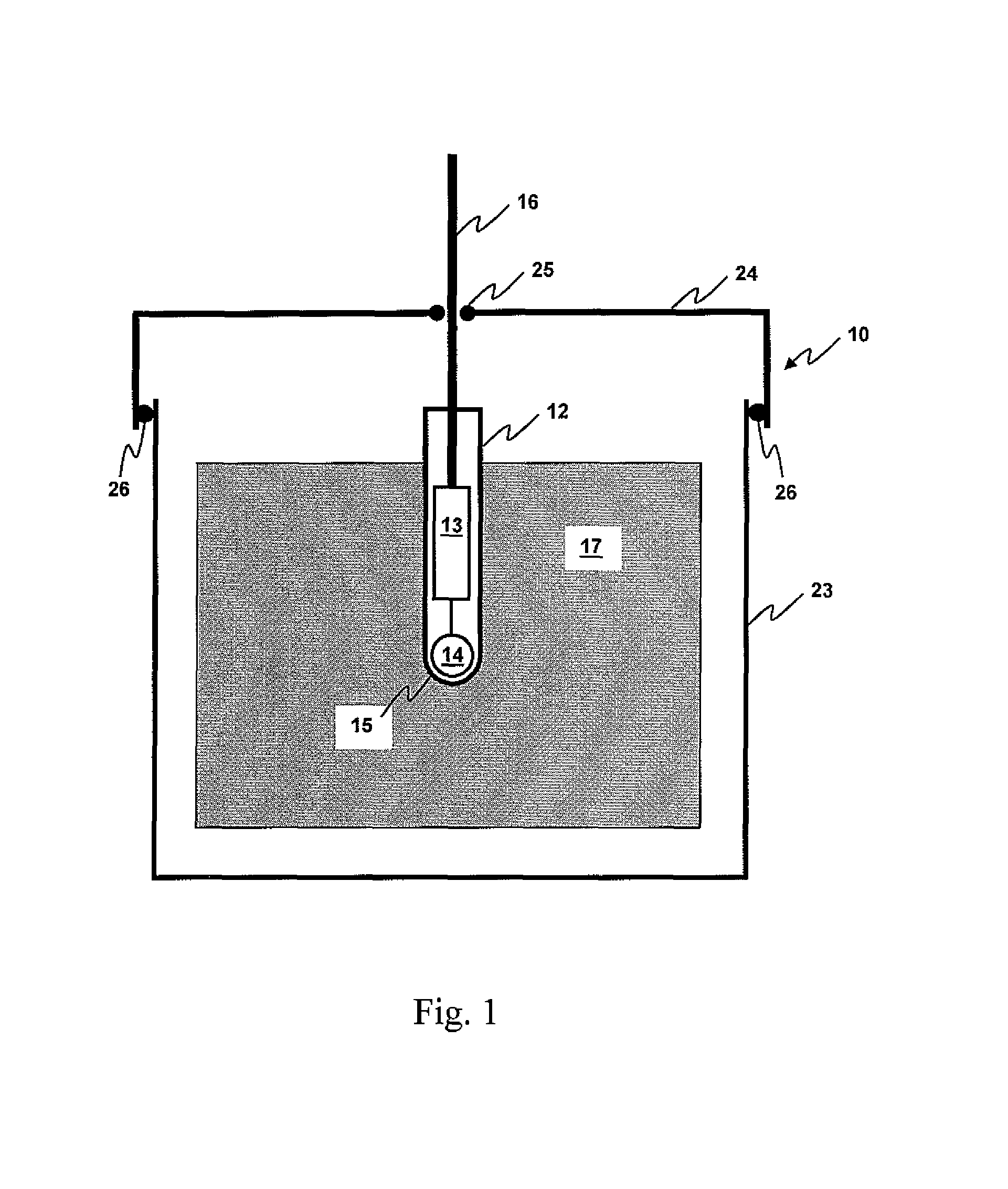
[0059]With reference to FIG. 1, there is illustrated a booster assembly shown generally at 10 comprising a connector, a booster and a detonator. The detonator 12 comprises a shell within which are internal electronic components 13 and a base charge 14 adjacent a percussion actuation end 15. A signal transmission line 16 is connected directly to the detonator, and specifically the internal components 13, via an end of the detonator opposite the percussion-actuation end. The booster includes a booster housing 23 within which is retained a quantity of explosive material 17. Typically, but not necessarily, the explosive material 17 may be in solid or semi-solid form and shaped to allow the detonator to be seated therein, such that the percussion-actuation end of the detonator is embedded in the explosive material. In this way, actuation of the base charge in the detonator may cause subseq...

example 2

Booster Assembly Comprising Connector, with Signal Transmission Line Connected to Electrically Conductive Bridge Elements

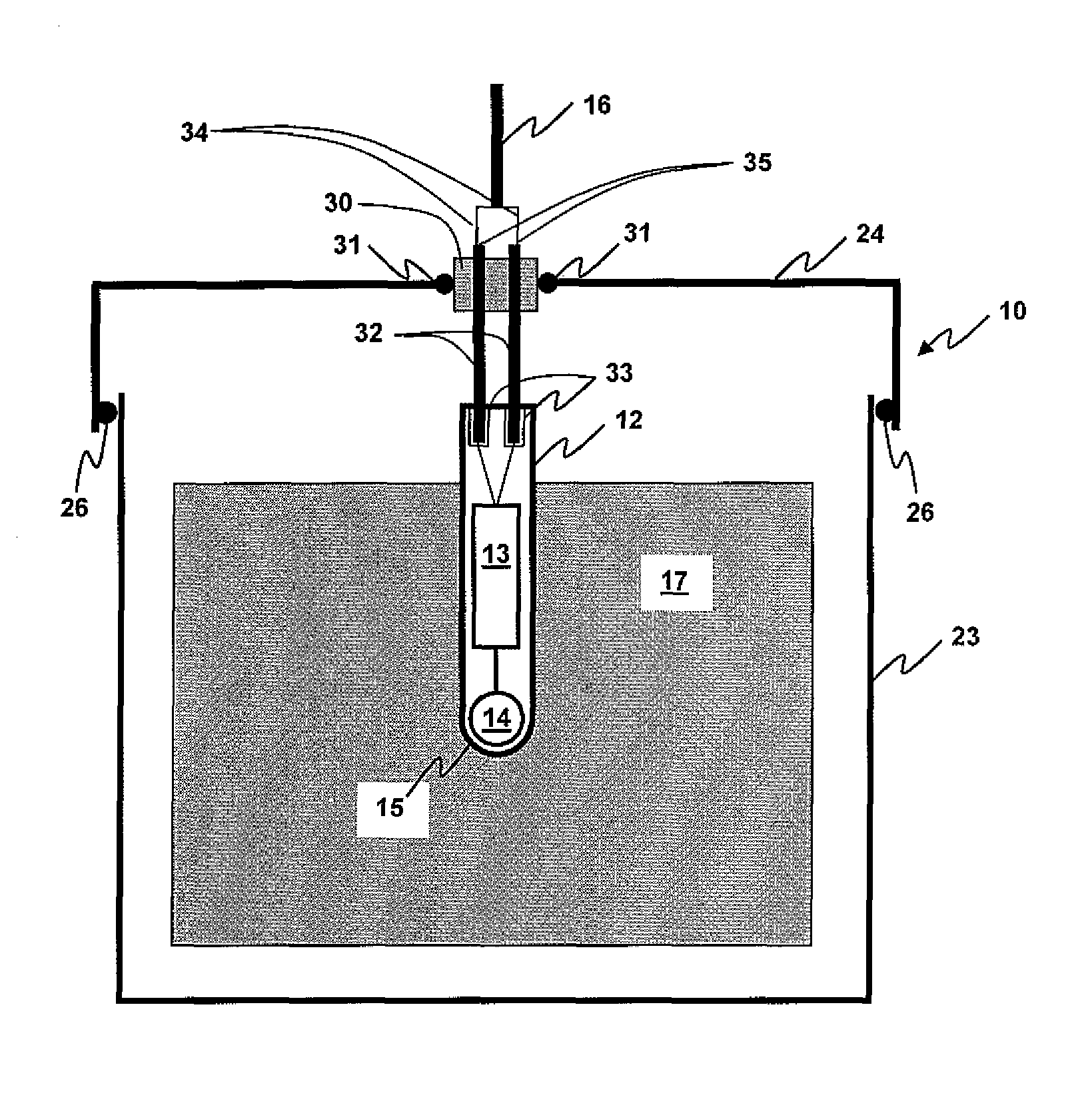
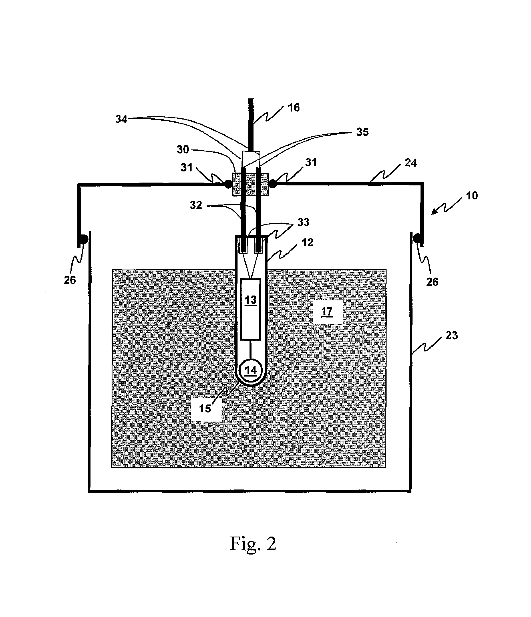
[0061]Turning now to FIG. 2, the embodiment illustrated is similar to that described in Example 1, with the exception that the signal transmission line retainer comprises electrically conducting bridge elements 32, extending through an optionally reinforced section 30 of attachment cap 24. Wires 34 of signal transmission line 16 are attached at interface 35 (e.g. a wire clasp or crimp) to the electrically conductive bridge elements 32. The bridge elements effectively form pins positioned to extend towards the detonator 12, to be received by sockets 33 in the detonator when the attachment cap 24 is properly attached to the booster housing 23. In this way, the bridge elements effectively “plug into” the detonator, thereby to provide electrical contact from the signal transmission line and the detonator. Preferably, attachment of the attachment cap to the housing hel...

example 3

Booster Assembly Comprising Connector, with Detonator Comprising Electrically Conductive Bridge Elements

[0064]Turning now to FIG. 3, there is shown a further embodiment of the booster assembly of the present invention. This booster assembly is similar to that described in Example 2, except that in this embodiment the electrically conductive bridge elements 32 form part of and extend from the detonator shell 12. In this way, the bridge elements 32 are received by sockets 40 forming part of the attachment cap 24, or optionally a reinforced portion 30 thereof. The sockets are in electrical contact with the wires 34 extending from signal transmission line 16, such that electrical contact is established between the signal transmission line and the detonator when the pins 32 are located therein. In accordance with Example 2, the detonator includes no trailing wires and may be transported to the blast site independently from the signal transmission line. Optionally, the connector may be fa...


PUM


Abstract

Mining operations frequently involve the use of electric or electronic delay detonators in operative association with an explosive charge contained in a booster. Disclosed herein are connectors for connecting a signal transmission line to a detonator associated with a booster. In this way, the connectors, at least in preferred embodiments, allow the production of a substantially sealed booster assembly having a secure electrical connection to a signal transmission line. Also disclosed are methods of producing substantially sealed booster assemblies, and methods for their use in mining operations.

Description

CROSS-REFERENCE TO RELATED APPLICATION[0001]This application claims the priority right of prior U.S. patent application 60 / 839,669 filed Aug. 24, 2006 by applicants herein.FIELD OF THE INVENTION[0002]The present invention relates to the field of blasting for mining operations. More specifically, the invention relates to electrical connection of detonators and associated boosters to other components of the blasting apparatus.BACKGROUND TO THE INVENTION[0003]A blasting apparatus may typically comprise an array of detonators and associated explosive charges, connected via wire signal transmission lines (e.g. branch lines and trunk lines) to one or more associated blasting machines. The detonators may receive a command signal to FIRE through the signal transmission lines. In the case of electronic detonators, the command signals may further include more complex instructions including, but not limited to, signals to ARM, DISARM, ACTIVATE, DEACTIVE, or SHUTDOWN the detonator, or may inclu...

Claims


Application Information

Patent Timeline
Patent Type & Authority Patents(United States)
IPC IPC(8): F42B3/02F42B3/10
CPCF42B3/103F42B3/26
Inventor ANDERSON, DAVID GEOFFREYBROCHOCKI, JAN MARKHUSK, PETER THOMASQUESNEL, CHRISTINE GENEVIEVE PIERRETTE
Owner ORICA EXPLOSIVES TECH PTY LTD
Why Eureka
Try Eureka