Method and assembly for breast immobilization

a breast and immobilization technology, applied in the field of breast immobilization, can solve the problems of breast tissue pliability, abnormal movement of breast tissue during treatment, and breast tissue naturally shifting,

Inactive Publication Date: 2010-11-09
BOSTON SCI SCIMED INC
View PDF24 Cites 17 Cited by
  • Summary
  • Abstract
  • Description
  • Claims
  • Application Information

AI Technical Summary

Benefits of technology

[0027]In an alternate preferred embodiment, the support member comprises first and second members slideably affixed to each other. These two members can be semi-circular in shape, and can be configured so that the second member is configured to slide within the first member. One of the two members can include one or more slots,

Problems solved by technology

This tissue pliability also complicates the taking of a percutaneous biopsy of a suspected abnormality—an important step in diagnosing breast cancer.
The difficulty arises because when a patient lies supine—i.e., on her (or his) back—the breasts fall back as a result of natural gravitational effects, and are compressed onto the costochondral wall, i.e. onto the rib cage.
First, since the abnormality is in a different location than it was when the patient was upright, it is difficult, without ongoing imaging assistance, to accurately aim the medical instrument—either an ablation probe or a biopsy needle—so that upon insertion it goes directly into the abnormality. This problem is exacerbated by the fact that as the medical instrument is inserted into the tissue, the breast tissue naturally shifts because of the force of insertion due to the breast's pliability. This in turn causes the abnormality to move around during treatment.
Second, and perhaps more significantly, since the abnormality is now closer to the rib cage, there is a serious risk that treatment will damage the neighboring costochondral wall and the surrounding healthy tissue. In addition, since the breast is compressed due to gravity, the abnormality may also be closer to the skin surface. Therefore, the ablation process has the potential to cause dermal blistering.
Third, as alluded to above, it is useful to apply an imaging technique during treatment, while the patient is lying supine. This enables the physician to monitor the progress of the treatment, and thus make suitable adjustments to avoid damaging healthy tissue on the one hand, and to ablate all of the cancerous tissue on the other hand. Imaging techniques typically make use of the fact that tumor tissue is denser than healthy tissue, and the images show this density differential as a visual contrast. However, when the breast is compressed while the patient is lying supine, the healthy tissue has the appearance of

Method used


Image

  • Method and assembly for breast immobilization
  • Method and assembly for breast immobilization
  • Method and assembly for breast immobilization

Examples


Embodiment Construction

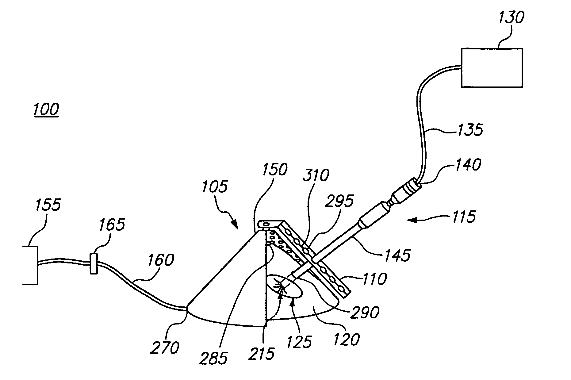
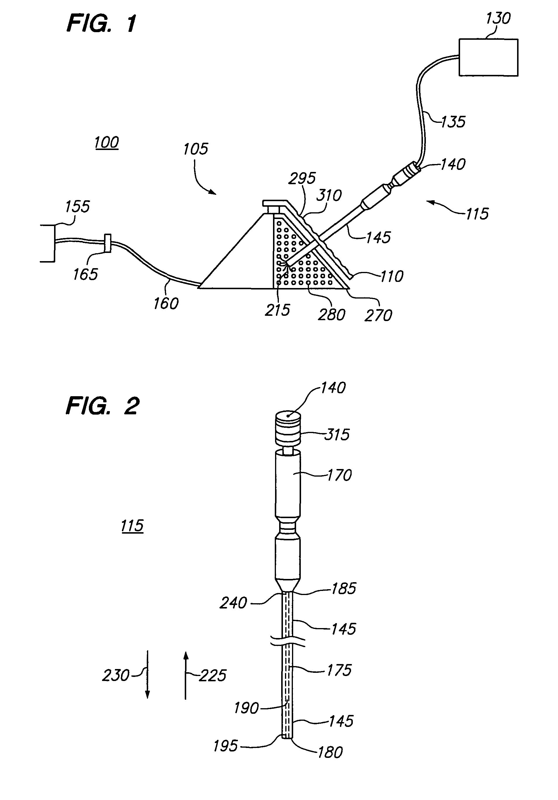
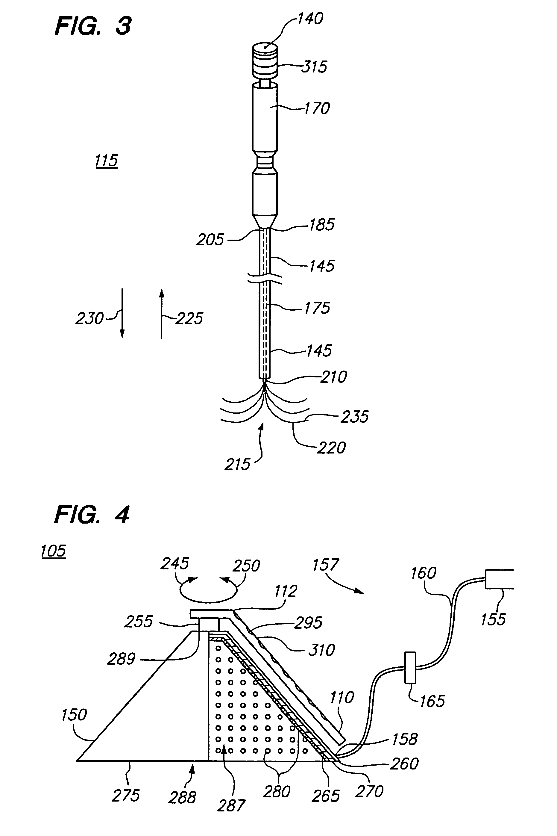
[0061]FIG. 1 illustrates a breast tissue ablation system 100 constructed in accordance with a preferred embodiment of the present invention. The ablation system 100 generally comprises an ablation probe assembly 115, configured for introduction into a breast of a patient to ablate target tissue, such as a tumor, a radio frequency (RF) generator 130 configured for supplying RF energy to the probe assembly 115 in a controlled manner, and a vacuum operated breast immobilization assembly 105 configured to lift the breast away from the patient's body and stabilize it relative to an associated medical device holder 110.

[0062]Referring specifically to FIGS. 2 and 3, the probe assembly 115 generally comprises a handle assembly 170, an elongated cannula 145, and an inner probe 175 slideably disposed within the cannula 145. The handle assembly 170 is mounted to the cannula 145. As will be described in further detail below, the cannula 145 serves to deliver the active portion of the inner prob...


PUM


Abstract

A device, method, and system are provided for immobilizing and stabilizing a breast in preparation for tumor ablation or biopsy while the patient is lying supine. The breast is lifted away from the chest wall of the patient, so that the tissue abnormality to be treated is also lifted away from the chest wall. This reduces the possibility of damage to the neighboring costochondral wall and the surrounding healthy tissue. The device includes a medical device holder that can be used to accurately aim a medical probe, and hold it in place during treating.

Description

FIELD OF THE INVENTION[0001]The field of the present invention relates to the medical treatment of breast tissue, and more particularly to breast immobilization in preparation for the treatment.BACKGROUND OF THE INVENTION[0002]Radio frequency (RF) energy can be used to ablate solid tissue, thus inducing localized tissue necrosis. RF energy is particularly useful in this capacity for inducing necrosis in sub-dermal lesions and tumors such as those found in cancers of the liver, stomach, kidney, lung, bowel, pancreas, and breast. The conventional delivery system for this sort of treatment is an electro-surgical probe, and one benefit to using such a probe is that it is much less invasive than a full surgical procedure to remove the pathology. As a consequence, recovery time, morbidity, and mortality are greatly reduced, and costs are lowered.[0003]As radio frequency thermal ablation (RFA) technology has been refined, it has become possible to ablate relatively large tumors using image...

Claims


Application Information

Patent Timeline
IPC IPC(8): A61B10/00A61B17/00A61B18/00A61B18/14A61B19/00
CPCA61B19/201A61B19/203A61B18/1477A61B19/20A61B2017/008A61B2018/00011A61B2018/1425A61B2018/143A61B2018/1475A61B2019/205A61B90/10A61B90/17A61B90/11A61B90/14A61B2017/3411
Inventor RIOUX, ROBERTDICARLO, PAUL
Owner BOSTON SCI SCIMED INC
Why Eureka
Try Eureka