Manufacturing method of semiconductor device

a manufacturing method and semiconductor technology, applied in solid-state devices, chemical vapor deposition coatings, reaction chambers of plasma cvd apparatuses, etc., can solve the problems of degradation of quality or uneven thickness of thin film formed over glass substrates, uneven surface standing wave effects, and uneven thickness of thin film, etc., to achieve favorable switching characteristics, improve the contrast of display panels, and improve the effect of quality

Inactive Publication Date: 2010-11-16
SEMICON ENERGY LAB CO LTD
View PDF8 Cites 41 Cited by
  • Summary
  • Abstract
  • Description
  • Claims
  • Application Information

AI Technical Summary

Benefits of technology

[0015]Liquid crystal panels are manufactured by processing a plurality of panels over a large-area glass substrate, which is called a mother glass, and then dividing them into panels with sizes that match sizes of television screens and computer screens. This is to reduce the cost per one panel, by taking out a plurality of panels form one mother glass. In the market for liquid crystal television sets, the screen size (panel size) is being rapidly increased and the retail price is being rapidly reduced. In order to improve productivity while accommodating these screen size increase and price reduction, size increase of the mother glass has been underway in recent years.

Problems solved by technology

In such cases, the effect of a surface standing wave becomes very pronounced and the plasma density distribution in a reaction chamber of the plasma CVD apparatus becomes uneven.
Consequently, a problem such as degradation of quality or unevenness of thickness of a thin film formed over the glass substrate occurs.

Method used


Image

  • Manufacturing method of semiconductor device
  • Manufacturing method of semiconductor device
  • Manufacturing method of semiconductor device

Examples


embodiment mode 1

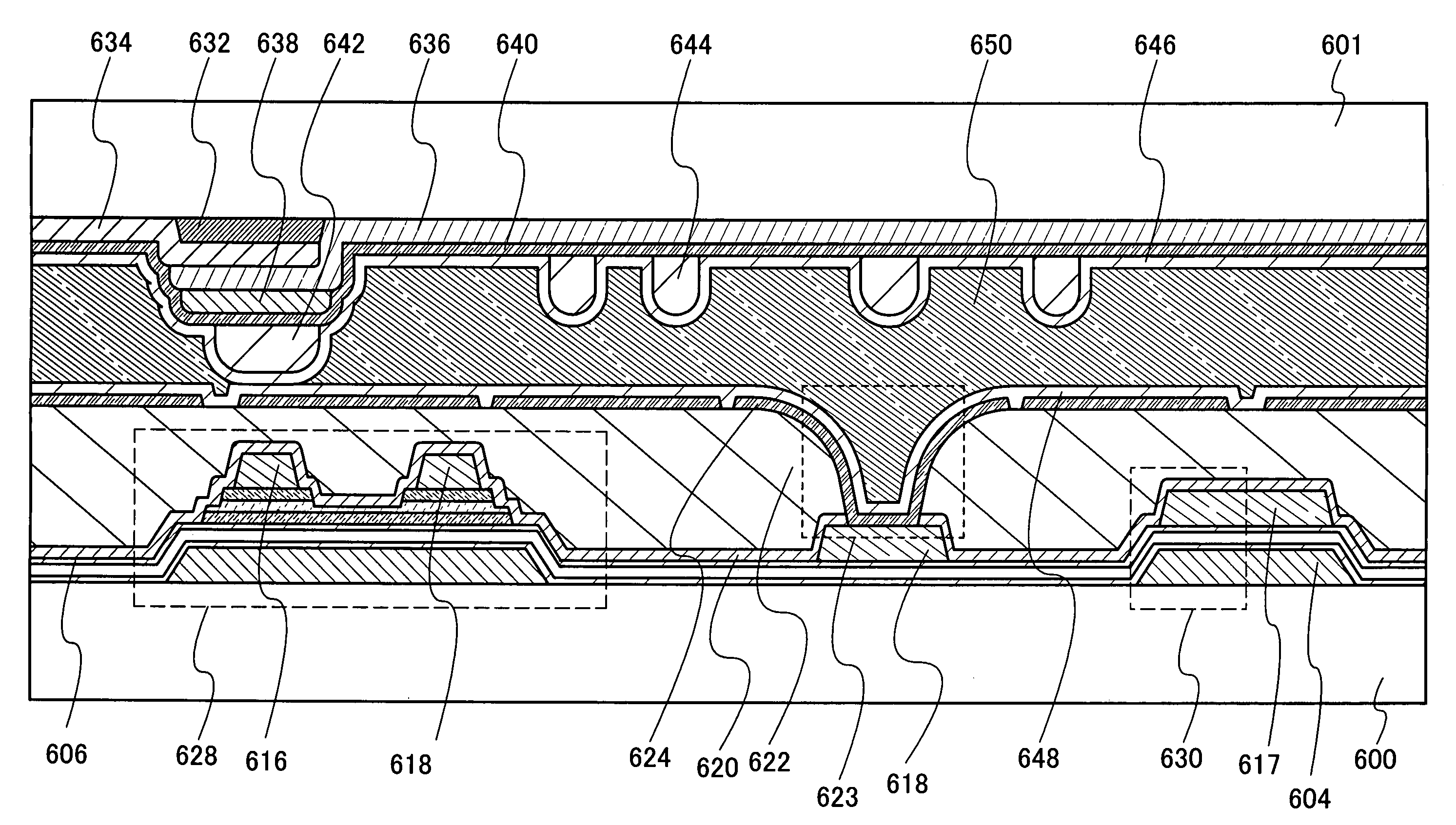
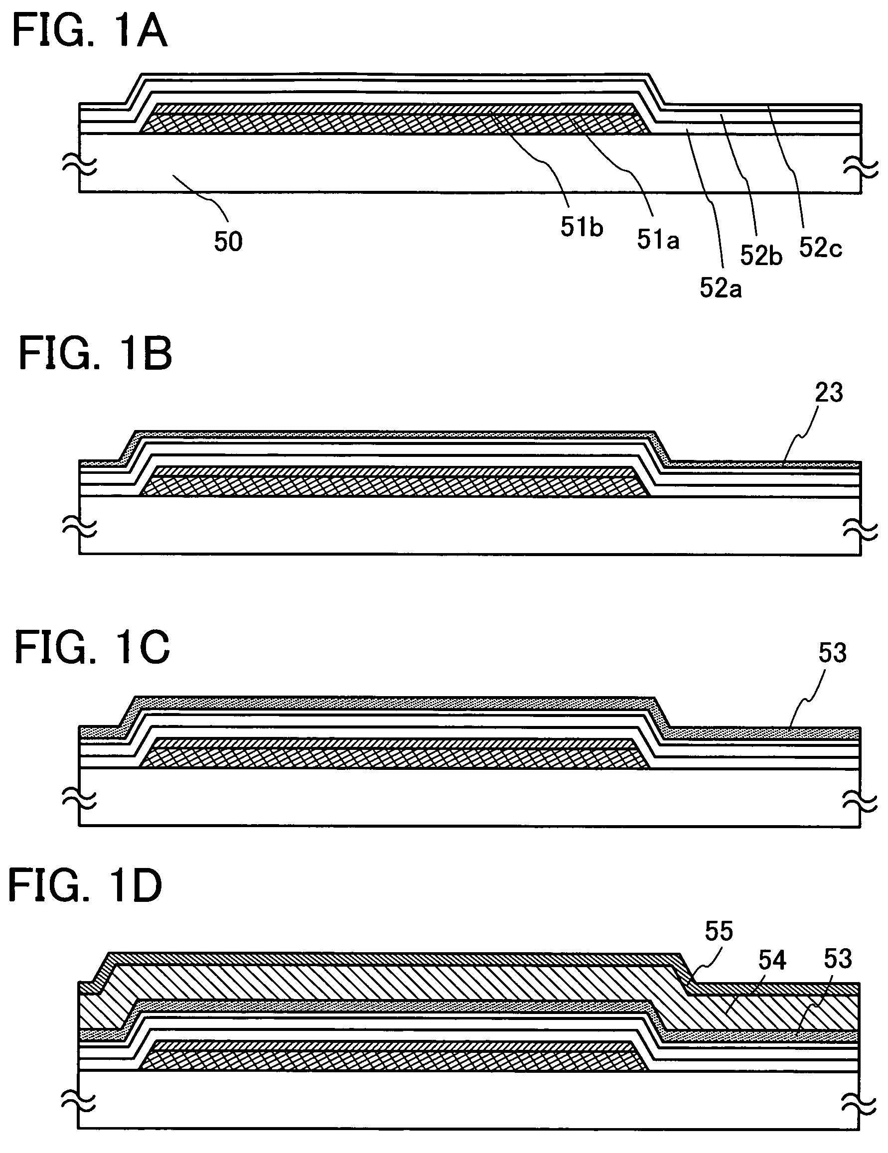
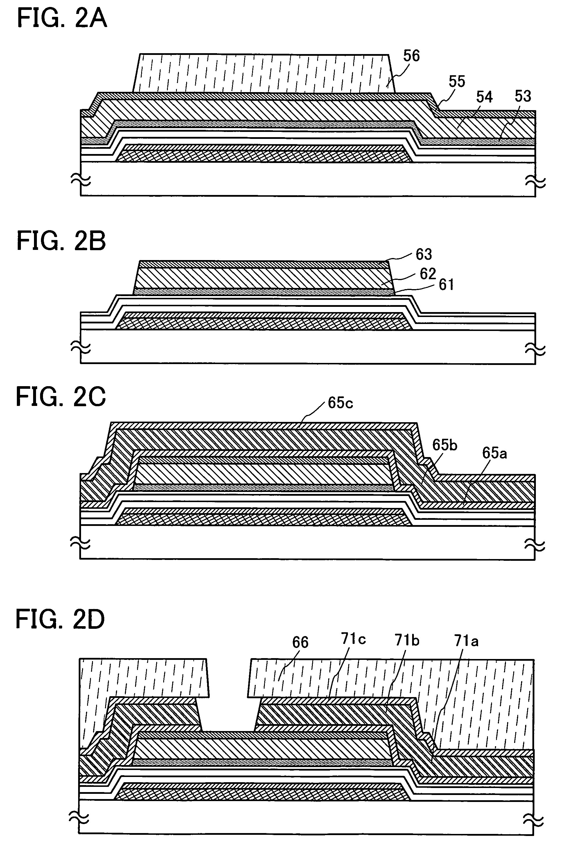
[0092]In this embodiment mode, a manufacturing process of a thin film transistor used for a liquid crystal display device is described with reference to FIGS. 1A to 1D, FIGS. 2A to 2D, FIGS. 3A to 3C, FIG. 4, FIG. 5, and FIG. 6. FIGS. 1A to 1D, FIGS. 2A to 2D, and FIGS. 3A to 3C are cross-sectional views showing a manufacturing process of a thin film transistor, and FIG. 4 is a top view showing a connection region of a thin film transistor and a pixel electrode in a single pixel. Further, FIG. 5 is a timing chart showing a formation method of a microcrystalline silicon film, and FIG. 6 is a cross-sectional view showing a structural example of a plasma CVD apparatus capable of generating glow discharge plasma by supplying two or more kinds of high-frequency powers with different frequencies.

[0093]An n-channel thin film transistor having a microcrystalline semiconductor film is more suitable for use in a driver circuit than a p-channel thin film transistor having a microcrystalline se...

embodiment mode 2

[0167]This embodiment mode shows an example of a multi-chamber plasma CVD apparatus suitable for formation of a gate insulating film, a microcrystalline semiconductor film, and an n+layer included in the TFT described in Embodiment Mode 1.

[0168]FIG. 10 shows one example of a multi-chamber plasma CVD apparatus provided with a plurality of reaction chambers. This apparatus is provided with a common chamber 123, a load / unload chamber 122, a first reaction chamber 100a, a second reaction chamber 100b, and a third reaction chamber 100c. This apparatus is a single wafer-processing type in which a substrate set in a cassette 124 in the load / unload chamber 122 is transferred to / from each reaction chamber by a transfer unit 126 in the common chamber 123. A gate valve 125 is provided between the common chamber 123 and each reaction chamber, so that processing in one reaction chamber does not affect processing in other reaction chambers.

[0169]The reaction chambers are sorted according to the k...

embodiment mode 3

[0176]This embodiment mode will describe a manufacturing process of a thin film transistor using a multi-chamber CVD apparatus which is different from that in FIG. 11 described in Embodiment Mode 2, with reference to FIG. 11. FIG. 11 shows the apparatus provided with three reaction chambers, whereas FIG. 11 is a top view of a multi-chamber CVD apparatus provided with four reaction chambers.

[0177]FIG. 11 shows a structure in which a fourth reaction chamber 100d is provided in addition to the structure of the multi-chamber CVD apparatus of FIG. 10. In FIG. 11, the same components as in FIG. 10 are denoted by the same reference numerals and detailed description thereof is omitted. Further, a combination of exhaust units shown in FIG. 11 is one example and the combination is not particularly limited thereto.

[0178]A gas supply unit 108b is connected to the fourth reaction chamber 100d. The structure of the high-frequency power supply units and the exhaust units is the same as in FIG. 10....


PUM

PropertyMeasurementUnit
temperatureaaaaaaaaaa

Abstract

An object is to provide a manufacturing method of a microcrystalline semiconductor film with favorable quality over a large-area substrate. After forming a gate insulating film over a gate electrode, in order to improve quality of a microcrystalline semiconductor film formed in an initial stage, glow discharge plasma is generated by supplying high-frequency powers with different frequencies, and a lower part of the film near an interface with the gate insulating film is formed under a first film formation condition, which is low in film formation rate but results in a good quality film. Thereafter, an upper part of the film is deposited under a second film formation condition with higher film formation rate, and further, a buffer layer is stacked on the microcrystalline semiconductor film.

Description

[0001]This application is based on Japanese Patent Application serial no. 2007-213102 filed with Japan Patent Office on Aug. 17, 2007, the entire contents of which are hereby incorporated by reference.BACKGROUND OF THE INVENTION[0002]1. Field of the Invention[0003]The present invention relates to a semiconductor device including a circuit, which is formed using a thin film transistor (hereinafter referred to as a TFT), and a manufacturing method thereof. For example, the present invention relates to an electronic device provided with, as a component, an electro-optical device typified by a liquid crystal display panel or a light-emitting display device having an organic light-emitting element.[0004]Note that in this specification, a semiconductor device refers to all types of devices which can function by utilizing semiconductor characteristics. An electro-optical device, a semiconductor circuit, and an electronic device are all included in the category of the semiconductor device.[...

Claims


Application Information

Patent Timeline
Patent Type & Authority Patents(United States)
IPC IPC(8): H01L21/00H01L21/84
CPCC23C16/509C23C16/515H01L29/04H01L29/78696H01L27/1288H01L29/458H01L29/4908H01L21/2053H01L29/66765
Inventor YAMAZAKI, SHUNPEITEDUKA, SACHIAKITORIUMI, SATOSHIFURUNO, MAKOTOJINBO, YASUHIRODAIRIKI, KOJIKUWABARA, HIDEAKI
Owner SEMICON ENERGY LAB CO LTD
Why Eureka
Try Eureka