

Pipe grip ring
a grip ring and pipe grip technology, applied in the direction of hose connection, fluid pressure sealing joint, sleeve/socket joint, etc., can solve the problems of unsuitable 3′′ steel unsuitable 3′′ pipe for the same wall thickness, and inability to meet the requirements of 3′′ steel pipe,
- Summary
- Abstract
- Description
- Claims
- Application Information
AI Technical Summary
Benefits of technology
Problems solved by technology
Method used
Image

Examples
Embodiment Construction
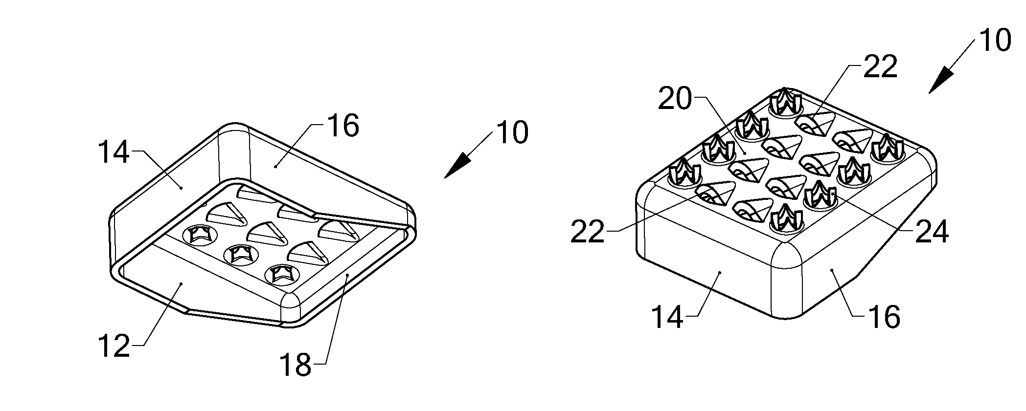
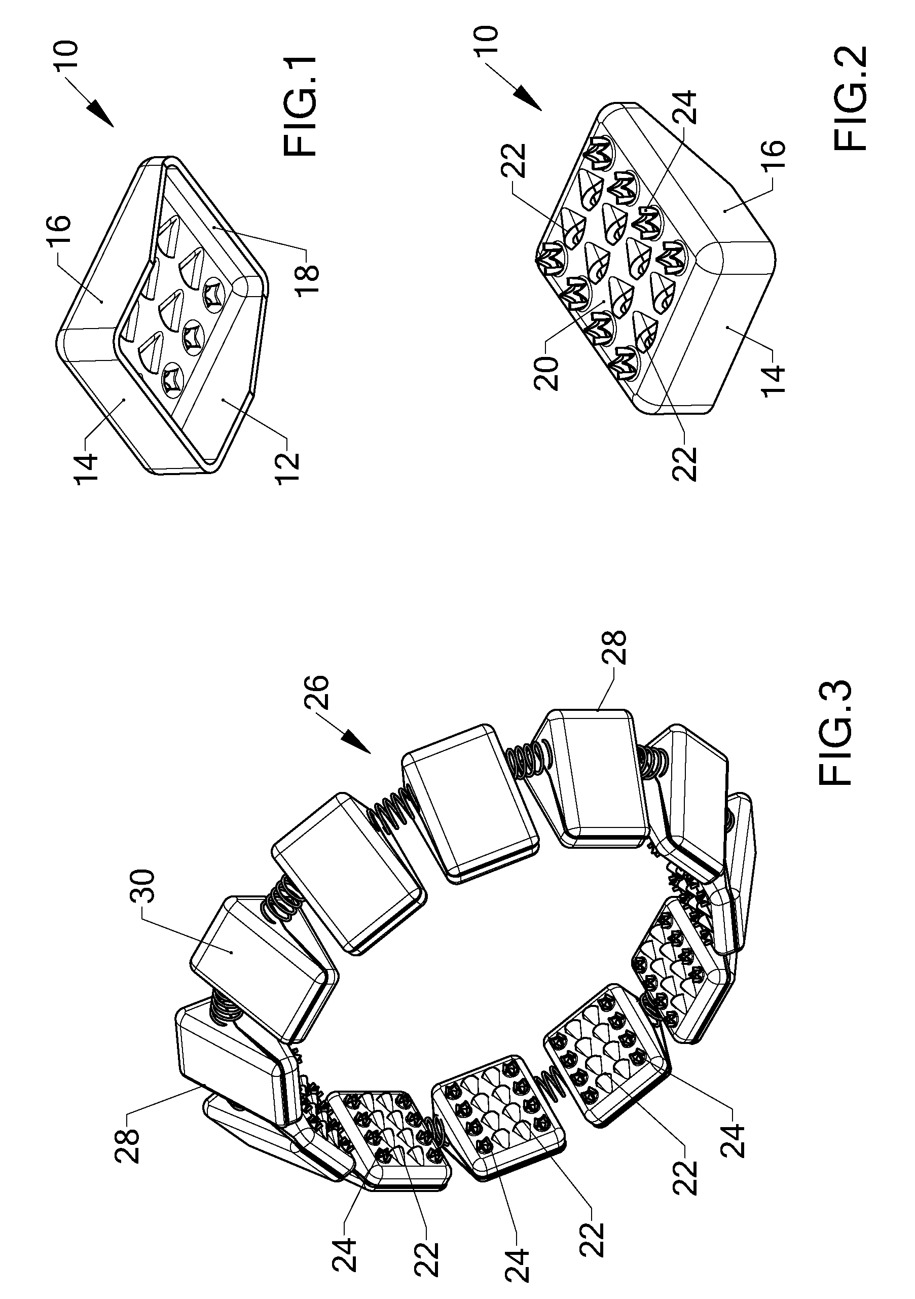
[0030]There is seen in FIGS. 1 and 2 a grip element 10 made of sheet steel. FIG. 1 shows the insides of the grip element where all walls 12, 141618 of the element are seen. In FIG. 2 the array of teeth of two different sizes is seen. The angled side walls 12, 16 convert the element 10 into a wedge-like structure. The exposed top outer surface 20 is a steel plate which is integral to all four walls.
[0031]The grip element 10 is provided with an array of large 22 and small 24 gripping teeth. The sharp edges of all teeth 22. 24 face the higher 14 of the two end walls, with the large teeth 22 projecting from the surface of the top outer surface 20 further than do the small teeth 24.
[0032]With reference to the rest of the figures, similar reference numerals have been used to identify similar parts.
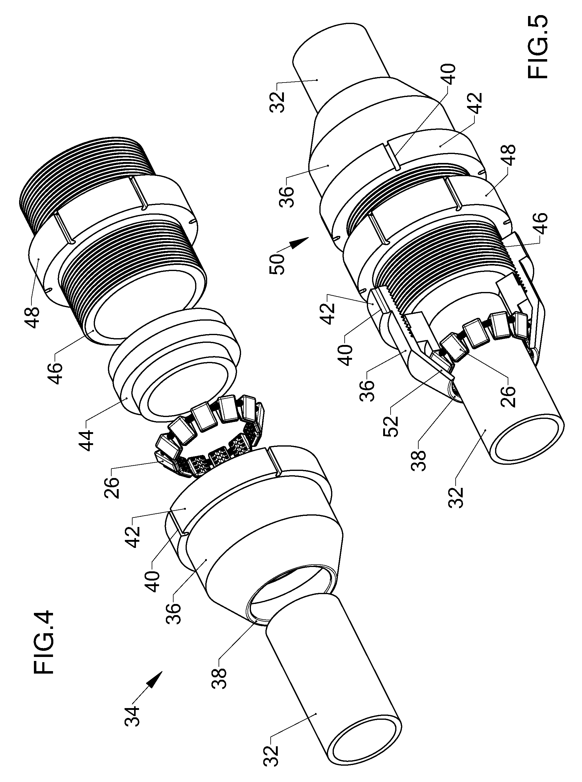
[0033]FIG. 3 illustrates a grip ring 26, for use in a pipe fitting to be described with reference to FIG. 4. The ring 26 retains several spaced-apart grip elements 28 which are radially evenly d...
PUM
 Abstract
Description
Claims
Application Information