Support crossbeam for an instrument panel

a technology for supporting crossbeams and instruments, which is applied in the direction of monocoque constructions, vehicle maintenance, superstructure sub-units, etc., can solve the problems of high weight, difficult adjustment between the three parts, and high cost of crossbeams manufactured in this manner, and achieve the effect of drastically reducing the number of parts forming the assembled crossbeams

Active Publication Date: 2010-11-30
AUTOTECH ENG SL
View PDF24 Cites 7 Cited by
  • Summary
  • Abstract
  • Description
  • Claims
  • Application Information

AI Technical Summary

Benefits of technology

[0017]The mentioned tubular portions with a closed cross-section provide a greater resistance to the end portions of the crossbeam without a significant increase of the size of the cross-section of the end portions or a significant increase in the weight of the crossbeam.
[0020]The general profile with an open cross-section comprises several transverse ribbings joined at their upper, lower and rear edges respectively to said upper, lower and rear walls. Said ribbings are generally in a plane substantially perpendicular to the upper, lower and bottom walls and are generally isolated from each other. Pernicious air entrapments which otherwise occur during the manufacture of parts by means of pressure die-casting technology due to the convergence and collision of flows of melted metal inside the mold when the ribbings are oblique and cross-linked are thus prevented. The mutually isolated perpendicular ribbings of the crossbeam of the present invention facilitate the flow of melted metal reducing the risk of air entrapments.
[0022]By virtue of a special arrangement of the mold parts, the crossbeam of the invention integrates most of the supporting configurations necessary for fixing the components normally associated to the crossbeam, such as the steering column, one or more airbags, the fuse box, the instrument panel, air conditioning ducts etc. Thanks to this, the number of parts forming the assembled crossbeam is drastically reduced.

Problems solved by technology

A crossbeam manufactured in this manner is very heavy and also very expensive because it requires separately manufacturing a large number of different support elements, which can sometimes be more than twenty, and the subsequent welding of such elements to the bar.
Its drawback is that the adjustment between the three parts is difficult and it has a high weight.
Crossbeams obtained from a single cast part having a profile with an open cross-section with a plurality of oblique and cross-linked ribbings, which are inconvenient during the casting process because they tend to produce air entrapments and therefore a deficient structural and metallurgic integrity, are also known in the state of the art.

Method used


Image

  • Support crossbeam for an instrument panel
  • Support crossbeam for an instrument panel
  • Support crossbeam for an instrument panel

Examples


Embodiment Construction

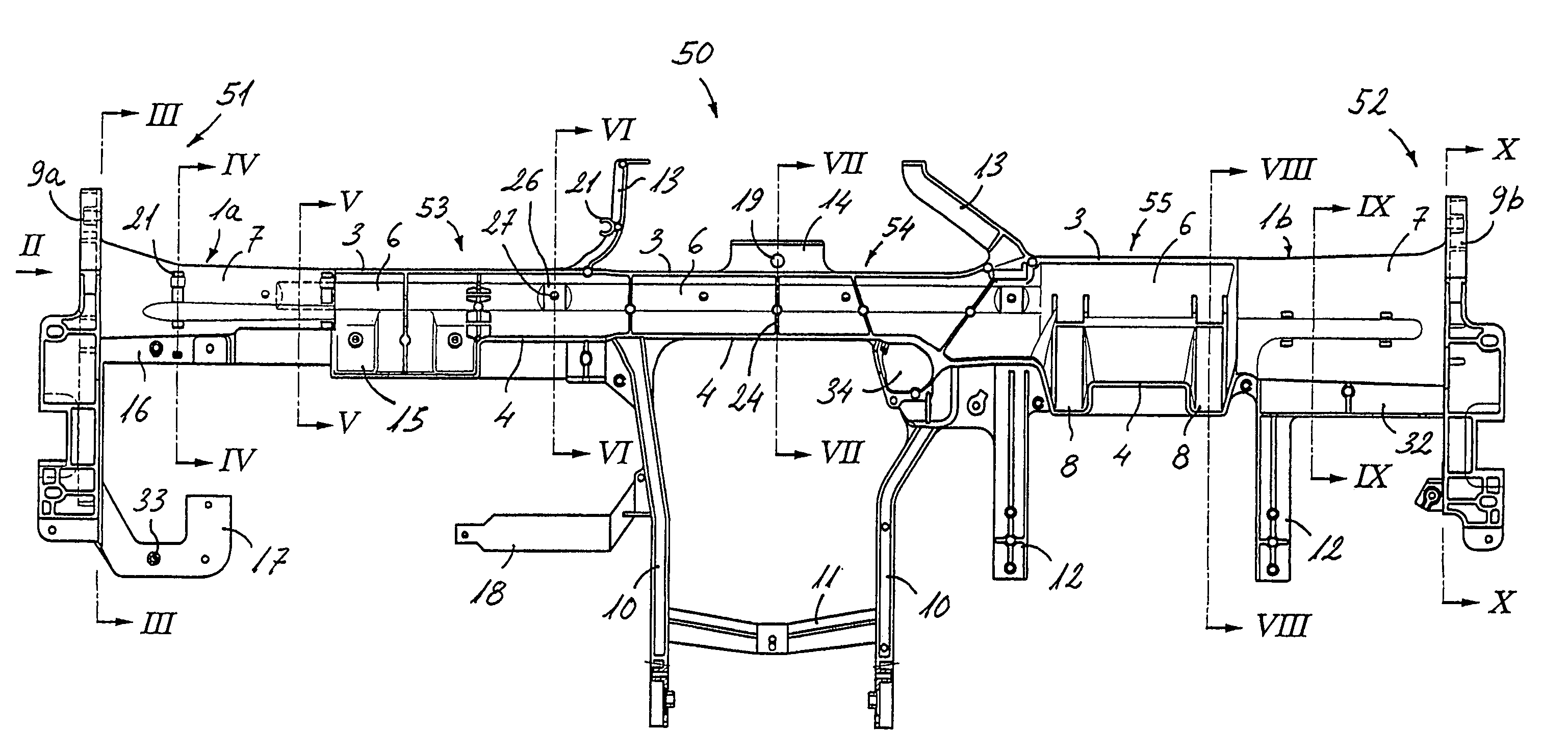
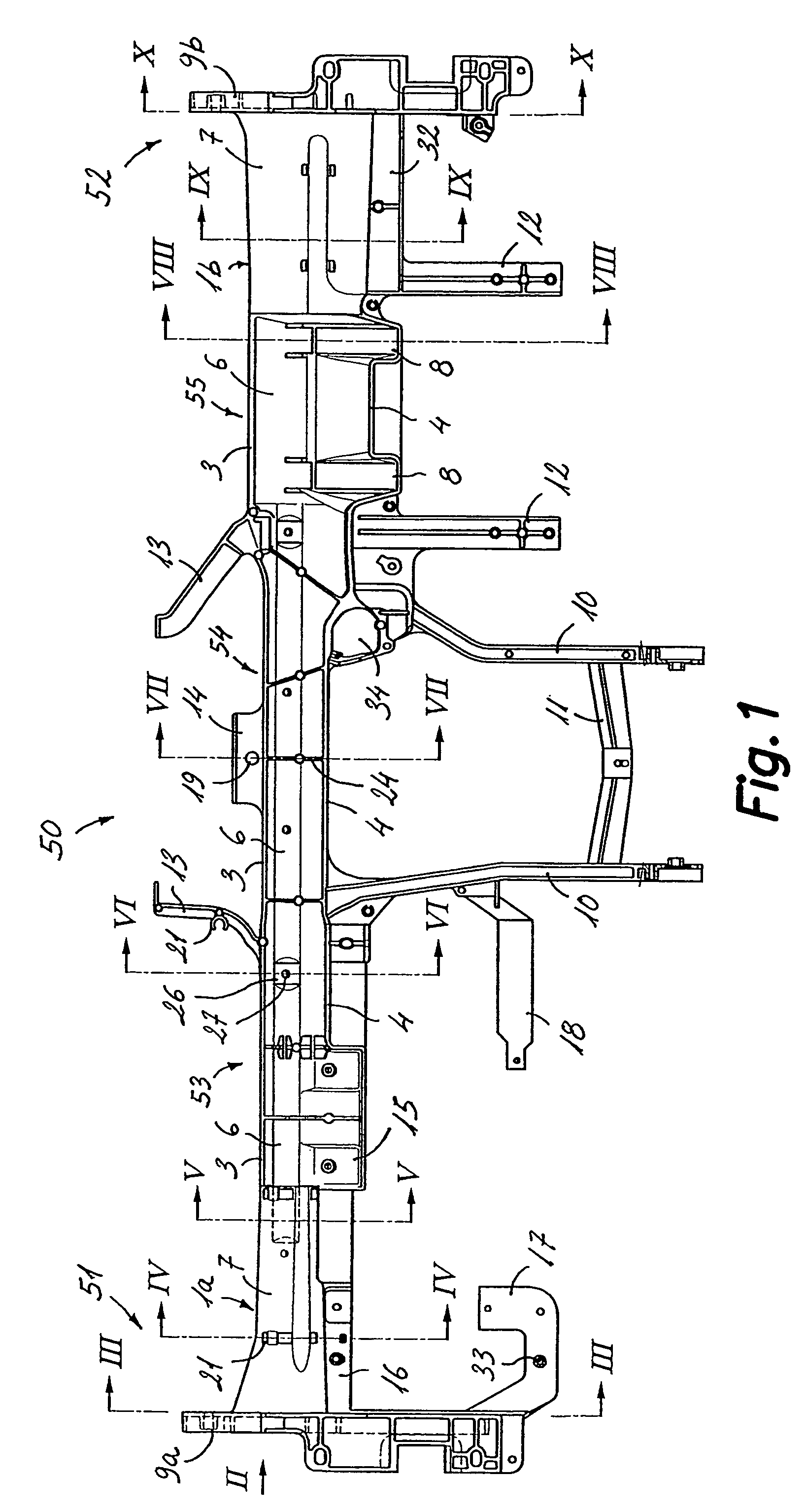
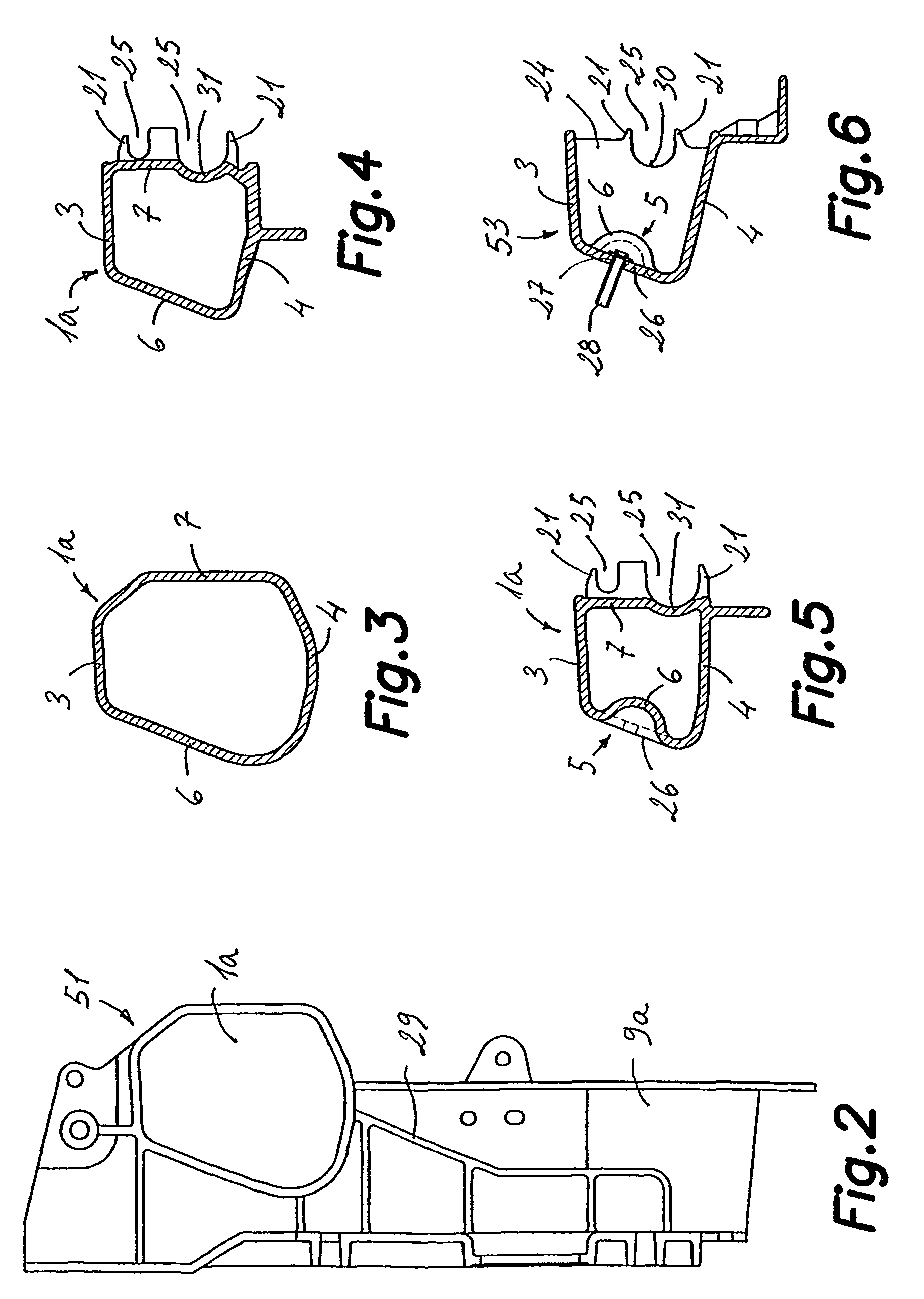
[0037]With reference to FIG. 1, a crossbeam for an instrument panel according to the present invention is designated by the reference number 50, which crossbeam is adapted to be assembled between two side elements of a frame of an automotive vehicle next to a front part of the interior. The crossbeam 50 is obtained from a single part 50 by pressure die-casting of a light metal alloy, preferably a magnesium alloy, although the invention is not limited to this alloy. The mentioned single part 50 has an elongated configuration and extends between first and second ends 51, 52 formed by respective first and second tubular portions la, lb with a closed cross-section (better shown in FIGS. 3-4 and 9-10 respectively) adapted to be demolded in the longitudinal direction of the crossbeam. Between said first and second tubular portions 1a, 1b with a closed cross-section, the crossbeam 50 has a general profile with an open cross-section adapted to be demolded in a transverse direction of the cr...


PUM


Abstract

The invention relates to a support crossbeam for an instrument panel to be assembled between two side elements of a frame of an automotive vehicle next to a front part of an interior. The crossbeam integrates several anchoring and supporting configurations for the steering column, several airbags, fuse boxes, ventilation system elements, sound equipment, among others, and is obtained by pressure die-casting of a light metal alloy, such a magnesium alloy, in an elongated single part extending between first and second ends. This single part has an open cross-section general profile, adapted to be demolded in a transverse direction of the crossbeam, with at least one tubular portion with a cross-section closed in at least one of said first or second ends, adapted to be demolded in the longitudinal direction of the crossbeam.

Description

[0001]This application is a U.S. National Phase Application of International PCT Application No. PCT / ES2004 / 000134, filed Mar. 26, 2004.FIELD OF THE ART[0002]The present invention relates to a crossbeam for an instrument panel of an automotive vehicle obtained by pressure die-casting of a light metal alloy, preferably a magnesium alloy, and integrating most of the configurations for anchoring and supporting different components.PRIOR ART[0003]Current automotive vehicles have a structural element in the form of a support crossbeam assembled on two side elements or pillars of the frame, next to a front part of the interior. Such crossbeam provides rigidity to the frame and acts as a supporter for several configurations for supporting different elements or components, including the steering column, one or more airbags, the fuse box, the instrument panel, air conditioning ducts, sound equipment etc. Most of these components need electrical connections of power supply and / or signals, suc...

Claims


Application Information

Patent Timeline
Patent Type & Authority Patents(United States)
IPC IPC(8): B62D25/14
CPCB62D25/145
Inventor PERARNAU RAMOS, FRANCESCSAEZ DE RAMON, RAFAMAS BURILLO, ALBERTINIGO GRIERA, OSCARINIGO, ANGEL
Owner AUTOTECH ENG SL
Why Eureka
Try Eureka