
High strength part and method for producing the same

a high-strength, part technology, applied in the field of members, can solve the problems of reducing the elongation or r value reducing the formability of steel sheets, and reducing the strength of steel sheets having a high strength, and achieve the effect of superior resistance to hydrogen embrittlemen

Active Publication Date: 2010-11-30
NIPPON STEEL CORP
View PDF28 Cites 21 Cited by
  • Summary
  • Abstract
  • Description
  • Claims
  • Application Information

AI Technical Summary

Benefits of technology

The present invention provides methods for producing high-strength parts that are resistant to hydrogen embrittlement and can exhibit a strength of about 1200 MPa or more after high-temperature shaping. These methods involve controlling the atmosphere in which the steel sheet is heated and shaped, and then cooling and hardening it in a mold to produce the desired shape. The resulting parts have superior strength and can be used in various applications such as high-temperature machining, aerospace, and automotive industries.

Problems solved by technology

However, steel sheet having a high strength may often exhibit a reduced elongation or r values and lower formability.
However, such techniques may be limited with respect to the strength that can be obtained.
However, heating and rapid cooling after shaping may lead to problems in obtaining shape precision.
For example, a member having a high strength, e.g., of over 1000 MPa, may exhibit undesirable hydrogen embrittlement (which may also be referred to as season cracking or delayed fracture).
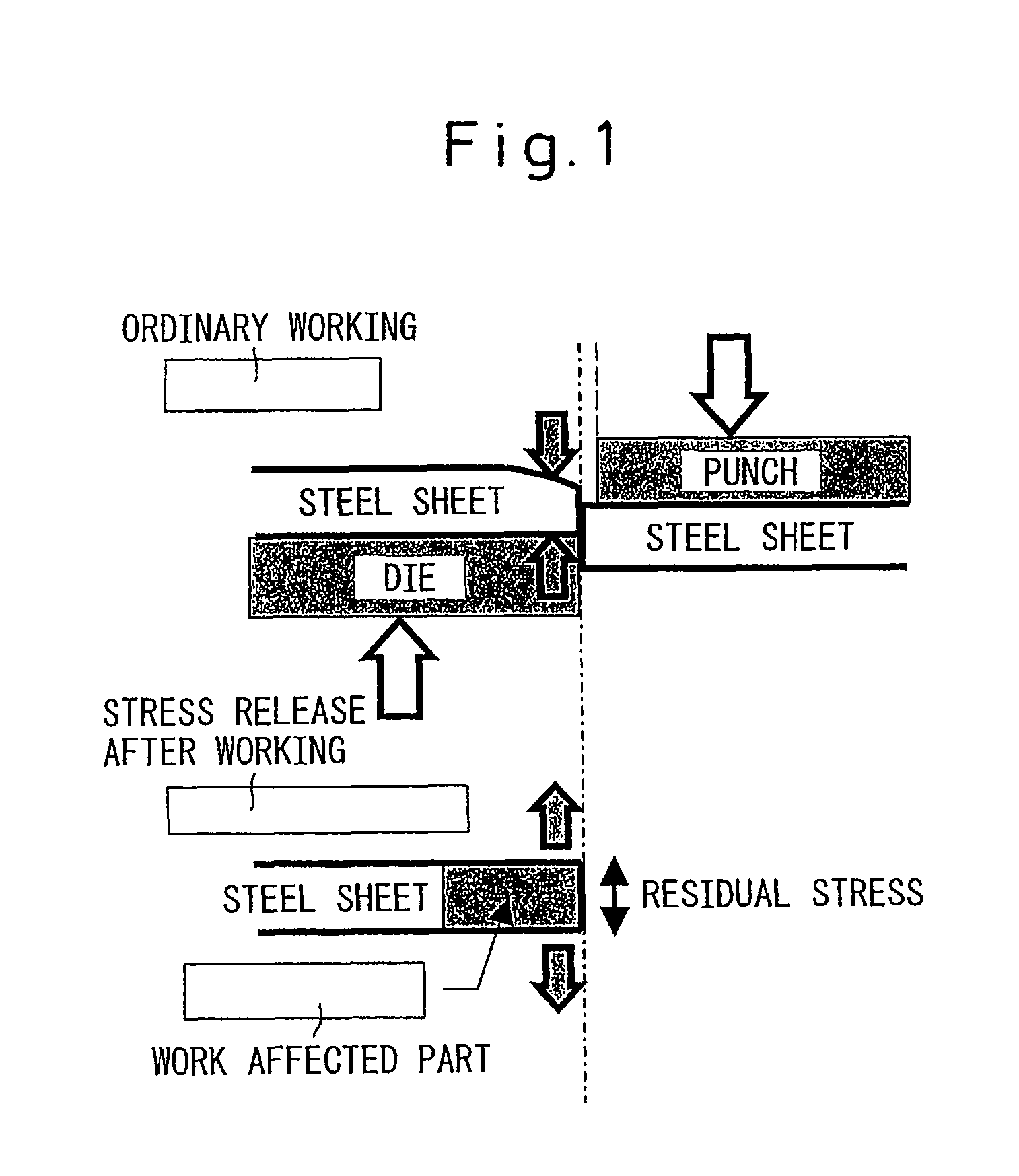
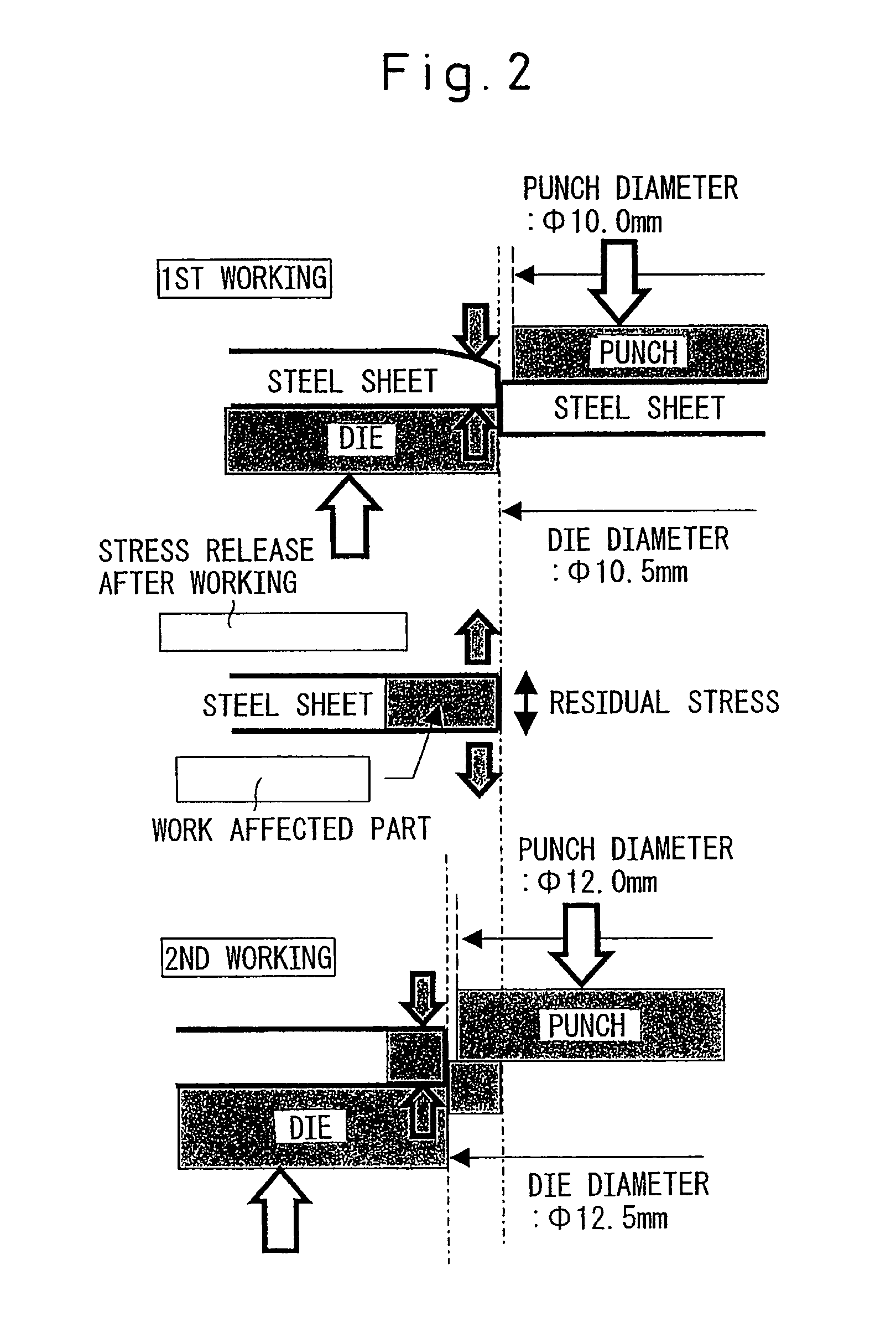
Further, residual stress associated with subsequent working can lead to greater susceptibility to hydrogen embrittlement.
Therefore, merely pressing at a high temperature may not solve such problems.
However, the mold structure may become complicated—which can be economically disadvantageous.
Thus, even if the steel sheet strength can be reduced somewhat and the residual stress after post-processing may also be reduced to a certain extent, hydrogen embrittlement may still occur if hydrogen remains in the steel.

Method used


Image

  • High strength part and method for producing the same
  • High strength part and method for producing the same
  • High strength part and method for producing the same

Examples


example 1

[0127]Slabs of steel having the chemical compositions shown in Table 1 were cast. These slabs were heated to between 1050 and 1350° C. and hot rolled at a finishing temperature between 800 and 900° C. and a coiling temperature between 450 and 680° C. to obtain hot rolled steel sheets having a thickness of 4 mm. Next, these sheets were pickled, then cold rolled to obtain cold rolled steel sheets having a thickness of 1.6 mm. These sheets were then heated to the austenite region of 950° C., above the Ac3 point, and hot shaped. The atmosphere of the heating furnace was varied with respect to the amount of hydrogen and the dew point. The conditions used are shown in Table 2 and Table 3. The tensile strengths were 1523 MPa and 1751 MPa.

[0128]When evaluating punch pieced parts, 100 mm×100 mm size pieces were cut from these shaped parts to obtain test pieces. The center parts were punched out by a F10 mm punch at a clearance of 15%, and the pieces were then secondarily worked under various...

example 2

[0133]Steel slabs having the chemical compositions shown in Table 4 were cast. These slabs were heated to between 1050 and 1350° C. and hot rolled at a finishing temperature of 800 to 900° C. and a coiling temperature of 450 to 680° C. to obtain hot rolled steel sheets having a thickness of 4 mm. Next, these sheets were pickled, then cold rolled to obtain steel sheets having a thickness of 1.6 mm. Further, parts of the cold rolled plates were treated by hot dip aluminum coating, hot dip aluminum-zinc coating, alloying hot dip galvanization, and / or hot dip galvanization. Table 5 shows the type of plating used for various samples. After plating, these cold rolled steel sheets and surface treated steel sheets were heated by furnace heating to the austenite region of the Ac3 point, e.g., to 950° C., and then were hot shaped. The atmosphere of the heating furnace was varied with respect to the amount of hydrogen and the dew point. The conditions used to process these samples are shown in...

example 3

[0139]Slabs having the chemical compositions shown in Table 4 were cast. These slabs were heated to 1050 to 1350° C. and hot rolled at a finishing temperature of 800 to 900° C. and a coiling temperature of 450 to 680° C. to obtain hot rolled steel sheets having a thickness of 4 mm. Next, these sheets were pickled, then cold rolled to obtain cold rolled steel sheets having a thickness of 1.6 mm. Further, parts of these cold rolled sheets were treated by hot dip aluminum coating, hot dip aluminum-zinc coating, alloying hot dip galvanization, and / or hot dip galvanization. Table 5 indicates the legends used for the plating types. After plating, these cold rolled steel sheets and surface treated steel sheets were heated in a furnace to above the Ac3 point, that is, above 950° C. and into the austenite region, then hot shaped. The atmosphere of the heating furnace was varied with respect to the amount of hydrogen present and the dew point. The conditions used are shown in Table 7.

[0140]A ...


PUM

PropertyMeasurementUnit
melting pointaaaaaaaaaa
tensile strengthaaaaaaaaaa
distanceaaaaaaaaaa

Abstract

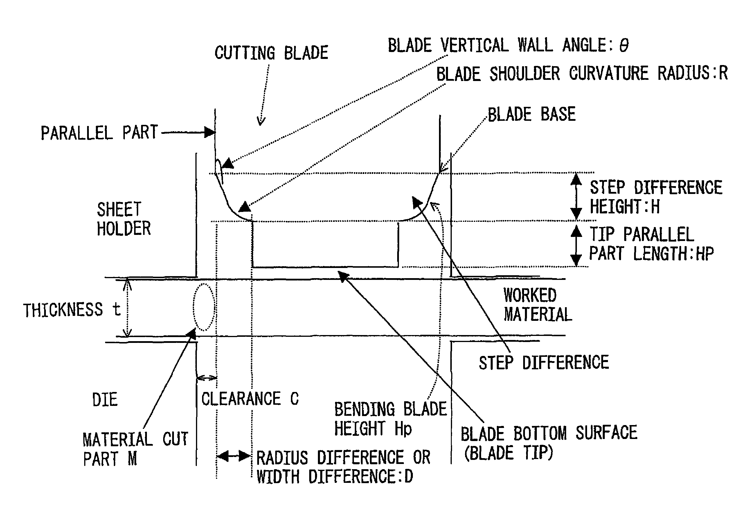
High-strength parts and a method for producing them can be provided, where such parts exhibit hydrogen embrittlement resistance and strength after high-temperature forming. For example, the atmosphere in a heating furnace can contain less than about 10% hydrogen and / or have a dew point of about 30° C. or less. The amount of hydrogen penetrating a steel sheet during heating can thereby be reduced. After forming, quench hardening in a die assembly and post-working can be performed. Post-working can include shearing followed by re-shearing or compression forming; punching with a cutting blade having a continuously reduced base width; punching with a tool having a curved blade and a protrusion at the tip of the cutting blade, where the curved blade may include a shoulder portion of given radius and / or angle; fusion cutting; etc. Tensile residual stresses after punching can be reduced and resistance to hydrogen embrittlement can be improved.

Description

CROSS-REFERENCE TO RELATED APPLICATION(S)[0001]This application is a national stage application of PCT Application No. PCT / JP2005 / 017441 which was filed on Sep. 15, 2005 and published on Mar. 23, 2006 as International Publication No. WO 2006 / 030971, the entire disclosure of which is incorporated herein by reference. This application claims priority from the International Application pursuant to 35 U.S.C. §365, and from Japanese Patent Application No. 2004-267797 filed Sep. 15, 2004, Japanese Patent Application No. 2004-267795 filed Sep. 15, 2004, Japanese Patent Application No. 2004-267792 filed Sep. 15, 2004, and Japanese Patent Application No. 2004-309779 filed Oct. 25, 2004, under 35 U.S.C. §119, the entire disclosures of which are incorporated herein by reference.FIELD OF THE INVENTION[0002]The present invention relates to members in which high strength is required, such as structural or reinforcing members which maybe used in an automobile, and more particularly to a part or co...

Claims


Application Information

Patent Timeline
Patent Type & Authority Patents(United States)
IPC IPC(8): C21D8/00
CPCC21D1/673C21D1/74C21D8/0205C21D9/0068C21D9/48C22C38/02C22C38/04C22C38/06C22C38/18C22C38/28C21D2211/008C22C38/38
Inventor KUSUMI, KAZUHISASATO, HIRONORIABE, MASAYUKIFUJITA, NOBUHIROSUZUKI, NORIYUKIHAYASHI, KUNIONAKAJIMA, SHINYAMAKI, JUNOOGAMI, MASAHIROKANDA, TOSHIYUKITAKAHASHI, MANABUTAKAHASHI, YUZO
Owner NIPPON STEEL CORP
Learn More