High reliability microwave mechanical switch

a microwave mechanical switch and high-reliability technology, applied in the field of electromechanical relays, can solve the problems of low switch lifetime, loss of reliability of rf switch, poor reliability of switch types, etc., to improve contact wiping action, and reduce contact bounce during switching operation.

a microwave mechanical switch and high-reliability technology, applied in the field of electromechanical relays, can solve the problems of low switch lifetime, loss of reliability of rf switch, poor reliability of switch types, etc., to improve contact wiping action, and reduce contact bounce during switching operation.

US7843289B1Active Publication Date: 2010-11-30SCI COMPONENTS

Image

  • High reliability microwave mechanical switch
  • High reliability microwave mechanical switch
  • High reliability microwave mechanical switch

Examples


Embodiment Construction

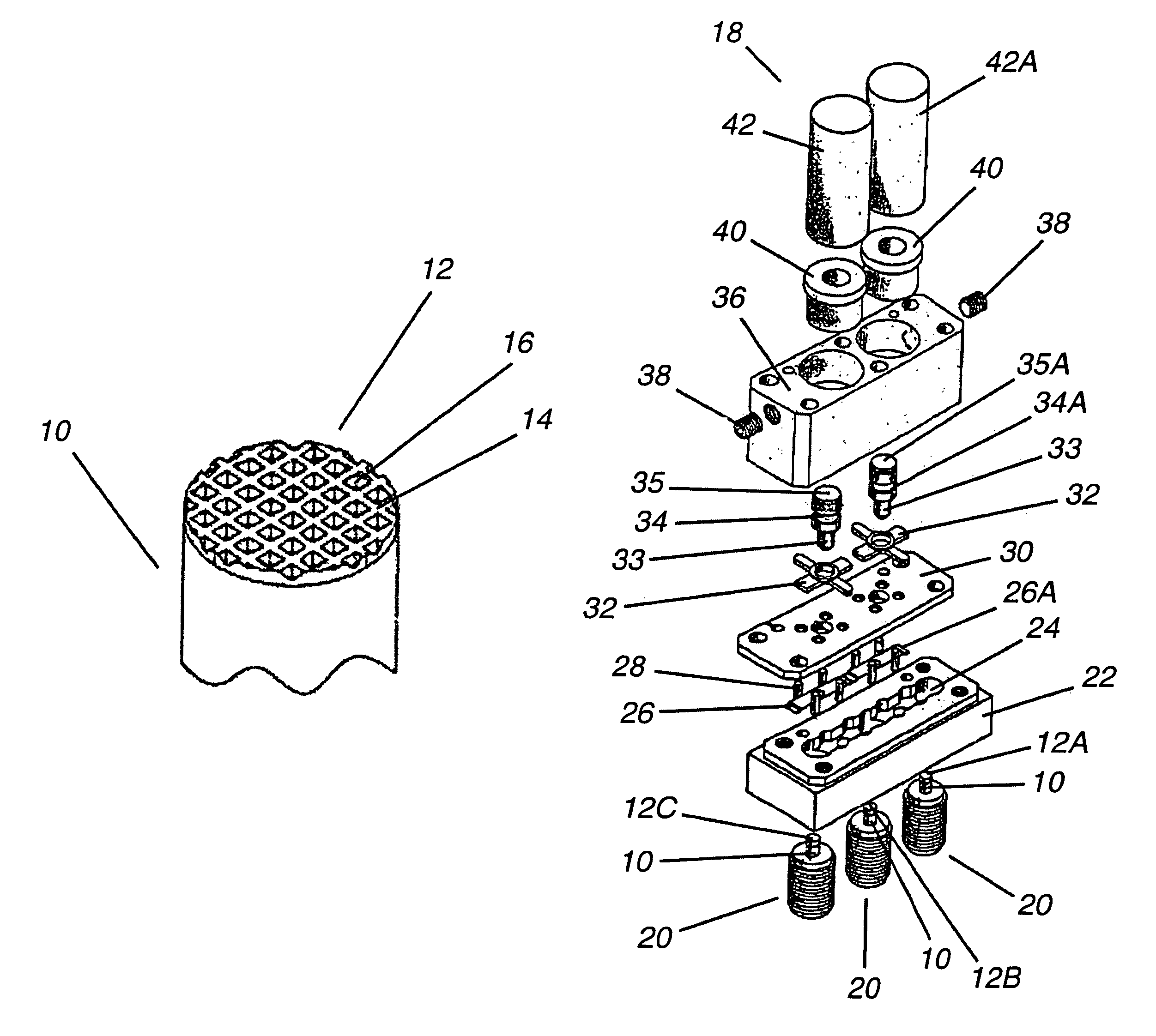
[0022]The invention described herein is a high reliability microwave mechanical switch incorporating probe tips contoured with a pattern of peaks and valleys and composed of a noble metal or an alloy of noble metals, and incorporating damper elements made of elastic material to reduce reed bounce during switch operation.

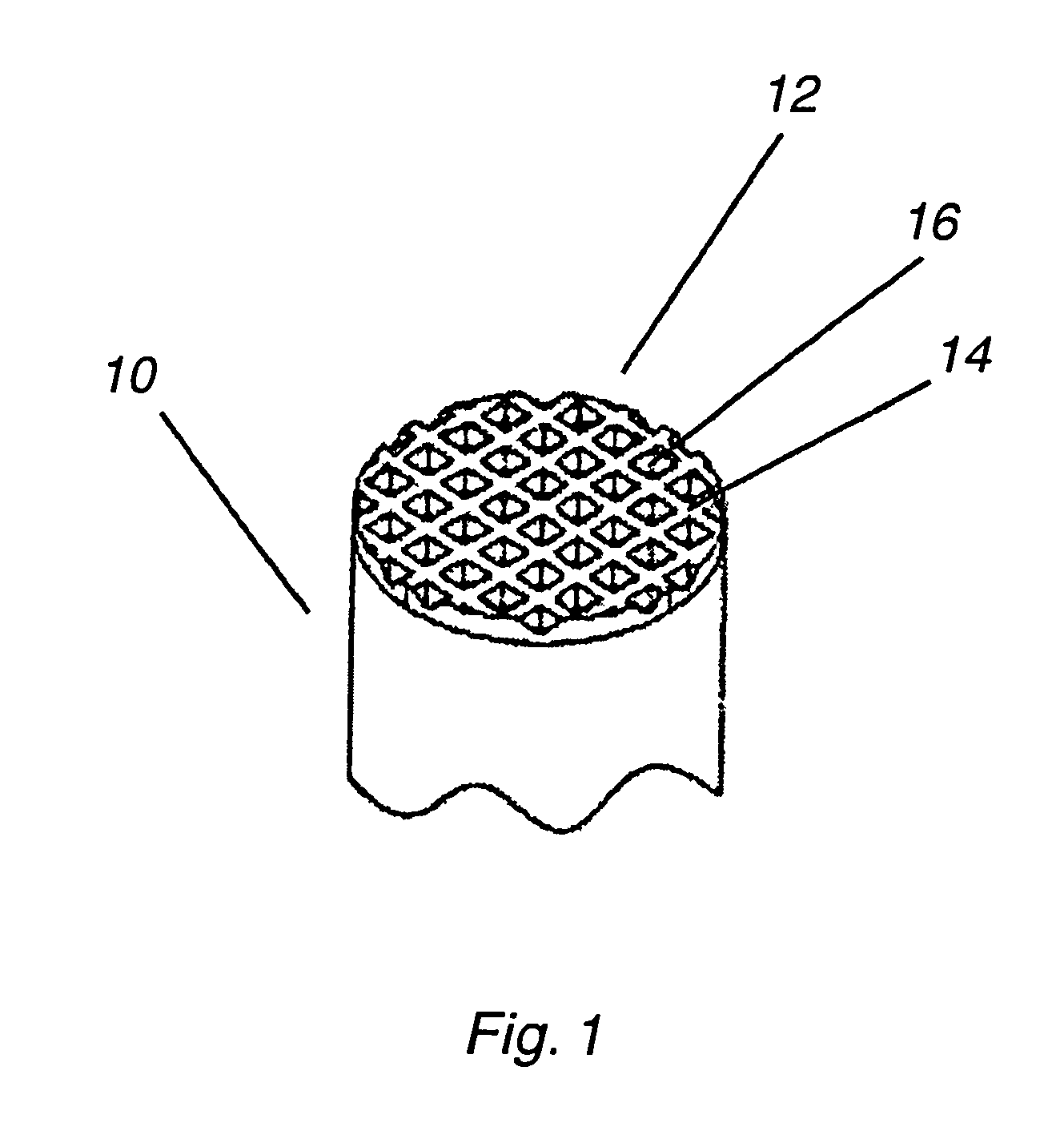
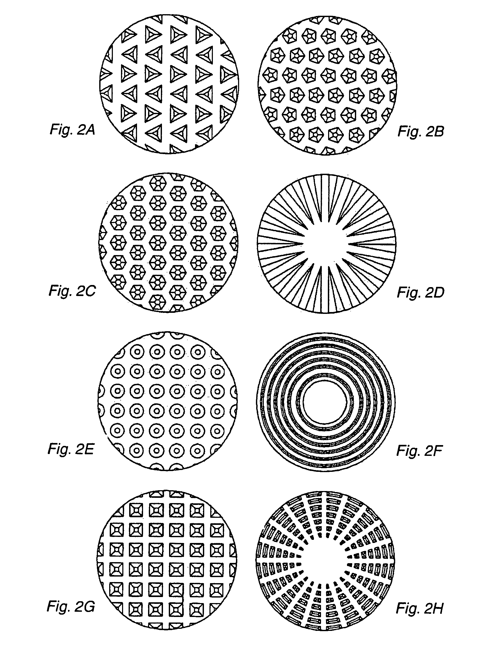
[0023]The terminal probe 10 is shown in FIG. 1 with a probe tip incorporating a pattern of peaks 14 and valleys 16. This particular pattern of peaks 14 and valleys 16 is the preferred embodiment known as a waffle pattern, after the shape commonly seen embossed in the surface of the food item of the same name. The peaks 14 provide a continuously clean electrical contact surface and the valleys 16 serve to capture any debris that may form as a result of contact wear experienced during contact make and break when switching. In the preferred embodiment, the contact elements are reeds made of thin and flexible strips of an alloy of noble metals. By manufacturing the probe...


PUM


Abstract

An improved electromechanical switch designed to operate at frequencies from DC through microwave has terminal probe tips that are formed from an alloy of noble metal and contoured with a pattern of peaks and valleys in order to provide better contact wiping operation and capture of wear debris. The switch incorporates damper elements to reduce switching contact bounce, thus providing increased contact life as well as higher quality signal switching.

Description

CROSS-REFERENCES TO RELATED APPLICATIONS[0001]This application is a continuation-in-part of U.S. patent application entitled ELECTROMECHANICAL RF SWITCH, Ser. No. 11 / 207,025 filed Aug. 19, 2005 now abandoned.BACKGROUND OF THE INVENTION[0002]1. Field of the Invention[0003]This invention relates to electromechanical relays for switching high-frequency signals with high reliability, stable insertion loss, stable return loss and high isolation.[0004]2. Description of the Prior Art[0005]Many different types of switches are known for the switching of radio frequency signals and other signals. Some switch types include spring actuated contacts, electromagnetic actuators, plungers with permanent magnets, articulated joints and other movable elements. Examples of these types of switches are shown in U.S. Pat. Nos. 6,340,923; 6,337,612; 6,204,740; 6,124,771; 5,894,255; 5,815,049; 5,724,014; 5,699,030; 5,652,558; and, 5,499,006. The switches using conductive reeds or similar elements generally...

Claims


Application Information

Patent Timeline
30 Nov 2010
Publication
US7843289B1
IPC
H01H53/00; H01H63/02; H01H7/16; H01H75/00; H01H77/00; H01H1/00; H01H67/02; H01H51/30; H01H1/12; H01H15/00; H01H51/34
CPC
H01H1/06; H01H50/305; H01H50/60; H01H51/2209; H01P1/11
Inventors
RAKLYAR, ARON; SIMKIN, GENNADY