Kerr effect compensated optical ring resonator

a ring resonator and kerr effect technology, applied in the field of kerr effect compensation of optical ring resonators, can solve the problem of large round-trip phase difference between the two waves, and achieve the effect of reducing or eliminating the net total non-linear phase shift accumulation very sharply

Active Publication Date: 2010-11-30
HONEYWELL INT INC
View PDF10 Cites 7 Cited by
  • Summary
  • Abstract
  • Description
  • Claims
  • Application Information

AI Technical Summary

Problems solved by technology

This effect, generated by the Kerr effect in silica glass, can produce a large round-trip phase difference between the two waves, and therefore an erroneous indication of rotation rate in the fiber optical resonator gyro.

Method used


Image

  • Kerr effect compensated optical ring resonator
  • Kerr effect compensated optical ring resonator
  • Kerr effect compensated optical ring resonator

Examples


Embodiment Construction

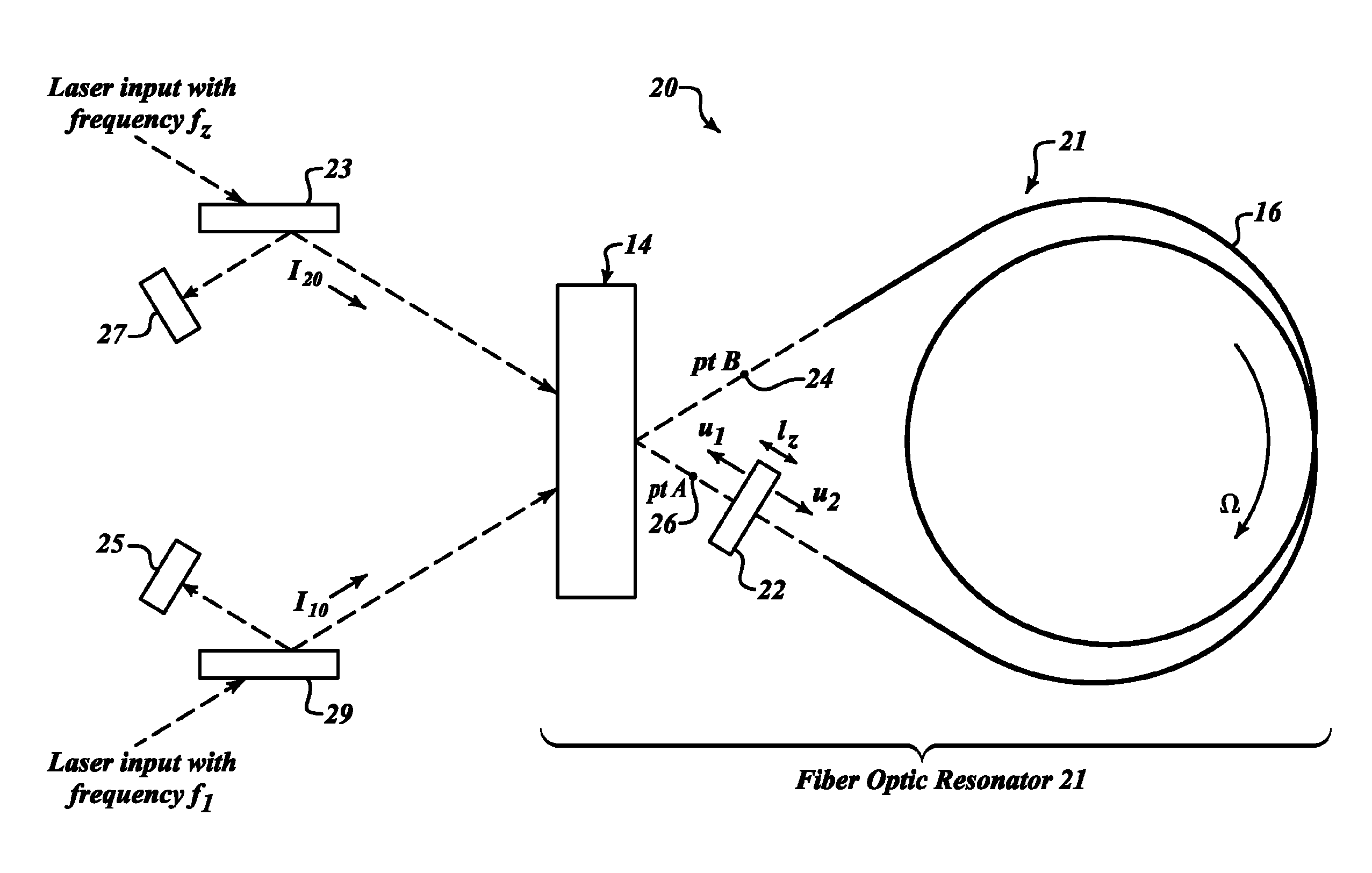
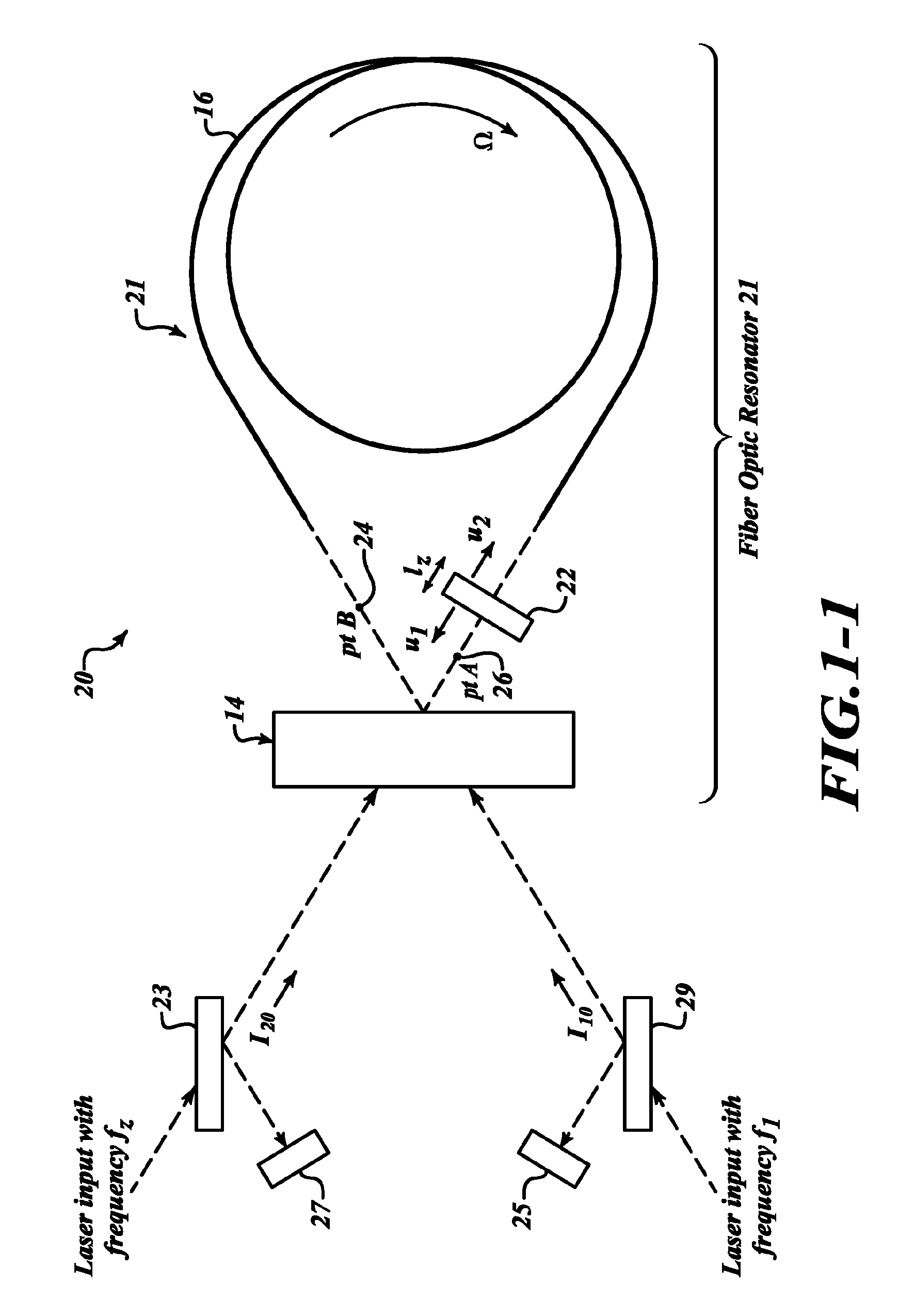
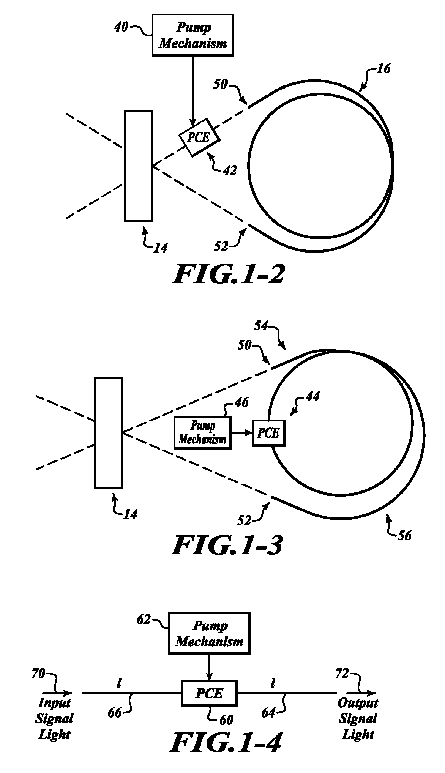
[0013]The present invention provides methods and systems for compensation of a regular positive nonlinearity in a fiber optical resonator gyroscope by introducing in the resonator one or more compensating devices capable of producing an effectively-negative nonlinearity or a reversal of the non-linear phase shift for an optical signal passing there-through. Another possibility is the deployment of phase conjugation using a non-linear element to compensate the non-linearity.

[0014]Examples of the above-mentioned effectively-negative compensating devices can be found in the following non-exhaustive list comprising: a nonlinear optical crystal, a poled polymer fiber, and a semiconductor wave guide.

[0015]The non-linear optical crystals (for example, the presently available potassium titanyl phosphate (KTP), potassium dihydrogen phosphate (KDP), barium borate optical crystals (BBO) or the like) are capable of receiving a light beam having a fundamental harmonic and producing there-inside ...


PUM

PropertyMeasurementUnit
sizeaaaaaaaaaa
sizeaaaaaaaaaa
lengthaaaaaaaaaa

Abstract

Systems and methods for compensating for nonlinear phase shift accumulation in an optical ring resonator. An example method includes sending a first beam in a clockwise direction around the optical ring resonator and sending a second beam in a counterclockwise direction around the optical ring resonator. Then, nonlinear phase shift accumulation of the first and second beams is compensated for within the optical ring resonator. Compensating includes creating a negative Kerr effect phase shift for each beam based on an estimate of accumulated positive Kerr effect.

Description

PRIORITY CLAIM[0001]This application claims the benefit of U.S. Provisional Application Ser. No. 60 / 948,341 filed Jul. 6, 2007, the contents of which are hereby incorporated by reference.BACKGROUND[0002]A physical factor that is known to limit the accuracy in a fiber optical resonator gyroscope (FOG) is non-linear Kerr effect. This nonlinear effect, that is a nonlinear phase shift dependent on the intensities of the clockwise (cw) and counterclockwise light waves propagating in the resonator, is accumulated by the two light signals while being transmitted via an optic fiber. This effect, generated by the Kerr effect in silica glass, can produce a large round-trip phase difference between the two waves, and therefore an erroneous indication of rotation rate in the fiber optical resonator gyro.[0003]The non-linear Kerr effect, for a light wave propagating in a single direction, gives an effective index of refraction coefficient of a material that changes with then=n0+K|E|2  (1)where K...

Claims


Application Information

Patent Timeline
Patent Type & Authority Patents(United States)
IPC IPC(8): G02B6/00G01C19/64H01S3/08G02F1/01
CPCG01C19/727G02F1/37G02F1/3544G02F2203/15
Inventor SANDERS, GLEN A.
Owner HONEYWELL INT INC
Why Eureka
Try Eureka