Method for monitoring of medical treatment using pulse-echo ultrasound

Inactive Publication Date: 2010-12-07
ETHICON ENDO SURGERY INC
View PDF365 Cites 93 Cited by
  • Summary
  • Abstract
  • Description
  • Claims
  • Application Information

AI Technical Summary

Benefits of technology

[0012]The present invention overcomes the limitations of the known art by mapping differences between a first and second echo signal, each signal being obtained at different instants of time. The first and second signals are typically separated by a small time interval. The first and second signals are processed, then a measure of the amplitude of the differences between the first and second signals is made (as contrasted with a measure of the differences in signal amplitude). This difference signal is then spatially filtered and scaled to quantify echo changes associated with chan

Problems solved by technology

Although this conventional B-Mode ultrasound imaging provides an effective means for imaging tissue that is in a static state, imaging of the tissue becomes more problematic when used in conjunction with thermal high-intensity ultrasound treatment.
As the tissue is ablated during treatment, the heating effects of ultrasound upon the tissue often result in qualitative changes in echo strength, causing brightness variations in the pixel display that do not consistently correspond spatially to the tissue being treated.
These brightness variations result in an image display that does not represent the actual shape a

Method used


Image

  • Method for monitoring of medical treatment using pulse-echo ultrasound
  • Method for monitoring of medical treatment using pulse-echo ultrasound
  • Method for monitoring of medical treatment using pulse-echo ultrasound

Examples


second embodiment

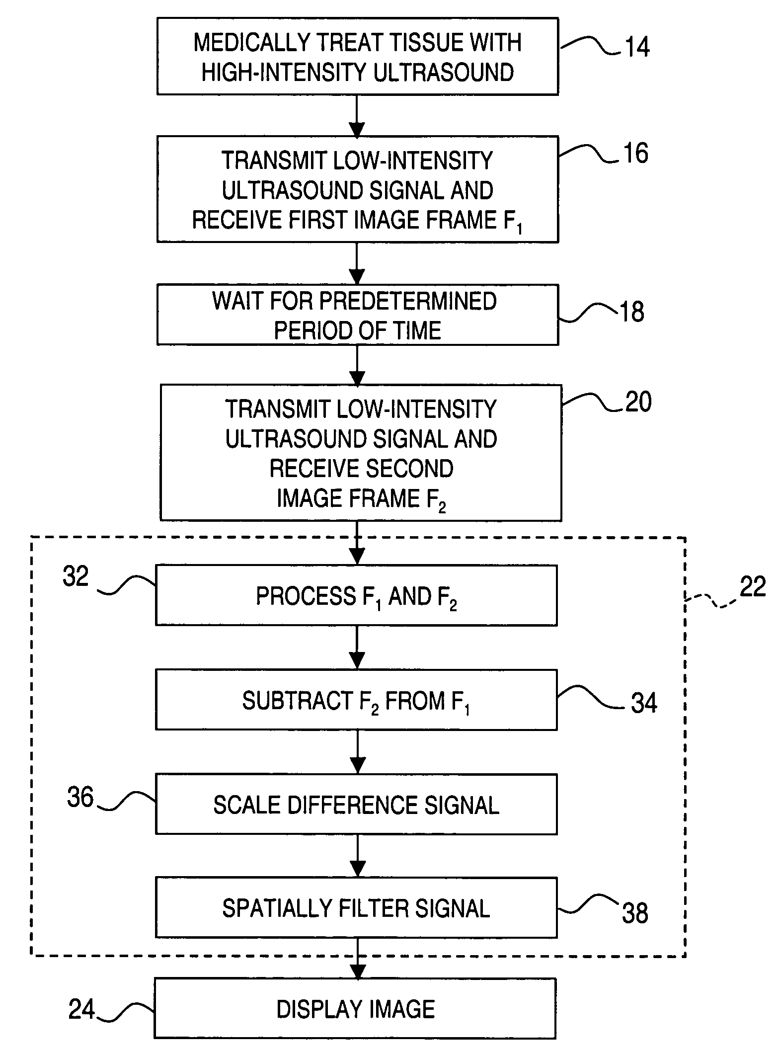
[0036]In the present invention, ultrasound images may be generated as depicted in FIGS. 10 and 11. At step 40 the tissue is medically treated with high-intensity ultrasound waves. At step 42 a succession of image frames, depicted as F1, F2, . . . Fn, are received. The image frames F1, F2, . . . Fn each contain a signal representing the same portion of the target tissue. At step 44 the image frames F1, F2, . . . Fn are mathematically grouped, such as by summing or averaging, to form a first image frame set labeled FS1, as shown in FIG. 11. After waiting a predetermined amount of time, as at step 46, a second set of image frames F1, F2, . . . Fn are received at step 48. At step 50 the second set of image frames F1, F2, . . . Fn are mathematically grouped, such as by summing or averaging, to form a second image frame set FS2 as shown in FIG. 11. The raw echo signals of image frame sets FS1 and FS2 may be processed at step 52, such as to derive complex analytic signals by means of a Hil...

third embodiment

[0037]In the present invention, smoothing of the image signal may alternatively be accomplished by using a plurality of image frames, as illustrated in FIGS. 12 and 13. The tissue is medically treated at step 60, then a set of image frames F1, F2, . . . Fn are received at step 62. A plurality of difference signals D1, D2, . . . Dn are computed at step 64. It should be noted that the difference signals may be computed using various arrangements of pairs of image frames. For example, difference signal D1 may be formed by subtracting F2 from F1; likewise, D2 may be formed by subtracting F3 from F2, as shown in FIG. 13. Other arrangements of image frame pairs may also be used, including (but not limited to) odd-numbered image frames (i.e., subtracting F3 from F1, etc.) and even-numbered image frames (i.e., subtracting F4 from F2, etc.). The pairings may be interlaced (i.e., subtracting F2 from F1, subtracting F3 from F2, etc.) or sequential (i.e., subtracting F2 from F1, F4 from F3, etc...

fourth embodiment

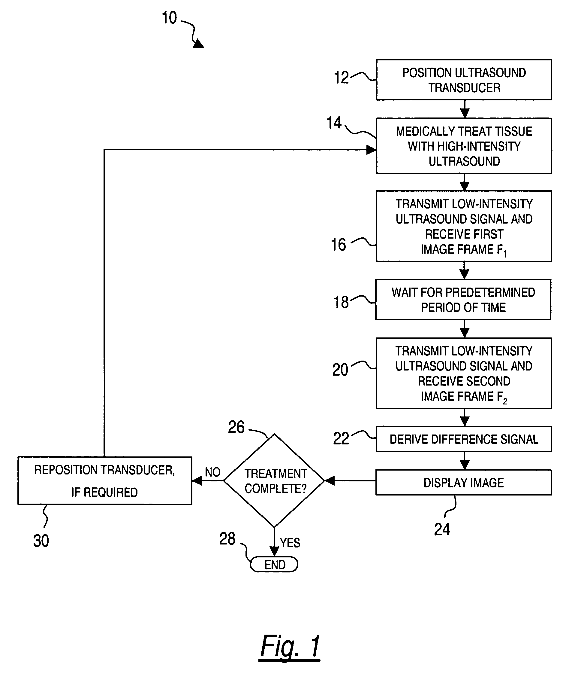
[0038]the present invention is shown in FIGS. 14 and 15 wherein a difference signal is derived using imaging frames generated both before and after medical treatment. At step 82 the ultrasound transducer is positioned proximate the targeted tissue to be medically treated. At step 84 a pre-treatment image frame F1 is generated from received ultrasound signals. Then, at step 86 the tissue is subject to a quantum of medical treatment, such as by ablating the tissue. After a quantum of medical treatment is administered, a second image frame F2 is generated at step 88. A difference signal is derived at step 90, using the data contained in image frames F1 and F2 in the same manner as previously described. An indication or image of the difference signal may be displayed at step 92. If treatment is determined to be complete at step 94, the method is ended at step 96. However, if the targeted tissue is determined to require additional treatment, the transducer may be re-positioned as necessa...


PUM


Abstract

A method for ultrasound imaging of anatomical tissue. A first signal is received from a first imaging ultrasound wave which has been reflected from a location in the anatomical tissue during a first time period. A second signal is received from a second imaging ultrasound wave which has been reflected from the location in the anatomical tissue during a later second time period, following a discrete medical treatment. The second signal is subtracted from the first signal to form a difference signal. The difference signal may be scaled, spatially filtered, then used to generate an indication, the indication showing the effect of the medical treatment in the location in the anatomical tissue.

Description

[0001]This is a continuation-in-part of application Ser. No. 10 / 153,241, filed May 22, 2002, now abandoned which claims priority to provisional application Ser. No. 60 / 294,135 filed May 29, 2001. The present invention relates generally to ultrasound, and more particularly, to an ultrasound medical imaging method.FIELD OF THE INVENTIONBackground of the Invention[0002]Ultrasound medical systems and methods include ultrasound imaging of anatomical tissue to identify tissue for medical treatment. Ultrasound may also be used to medically treat and destroy unwanted tissue by heating the tissue. Imaging is done using low-intensity ultrasound waves, while medical treatment is performed with high-intensity ultrasound waves. High-intensity ultrasound waves, when focused at a focal zone a distance away from the ultrasound source, will substantially medically affect tissue in the focal zone. However, the high-intensity ultrasound will not substantially affect patient tissue outside the focal zo...

Claims


Application Information

Patent Timeline
IPC IPC(8): A61B8/00A61B18/00A61B8/08A61B8/12A61B10/00A61B10/02A61B17/22A61B17/28A61B17/32A61B17/34A61B19/00A61N7/00A61N7/02G01S15/89H04R17/00
CPCA61B8/08G01S15/899A61B8/4488A61B8/5238A61B17/320092A61N7/022A61B8/12A61B10/0233A61B17/22012A61B17/2202A61B17/29A61B2019/5276A61B2019/528A61B2019/5429A61B2019/5475A61N2007/0078A61B2090/378A61B2090/3784A61B2090/3929A61B2090/3975A61B8/14A61B8/5207A61B8/5276
Inventor MAST, T. DOUGLASFAIDI, WASEEMMAKIN, INDER RAJ S.BARTHE, PETER G.SLAYTON, MICHAEL H.
Owner ETHICON ENDO SURGERY INC
Why Eureka
Try Eureka