
Method and system for patching instructions in a shader for a 3-D graphics pipeline

a graphics pipeline and instruction technology, applied in the field of graphics processors, can solve the problems of difficult repair of scheduling process errors, general inability to modify scheduling process modifications, and suffer performance of shader b>110/b>, and achieve the effect of expanding the functionality of scheduling process and high level

Active Publication Date: 2010-12-14
NVIDIA CORP
View PDF15 Cites 29 Cited by
  • Summary
  • Abstract
  • Description
  • Claims
  • Application Information

AI Technical Summary

Benefits of technology

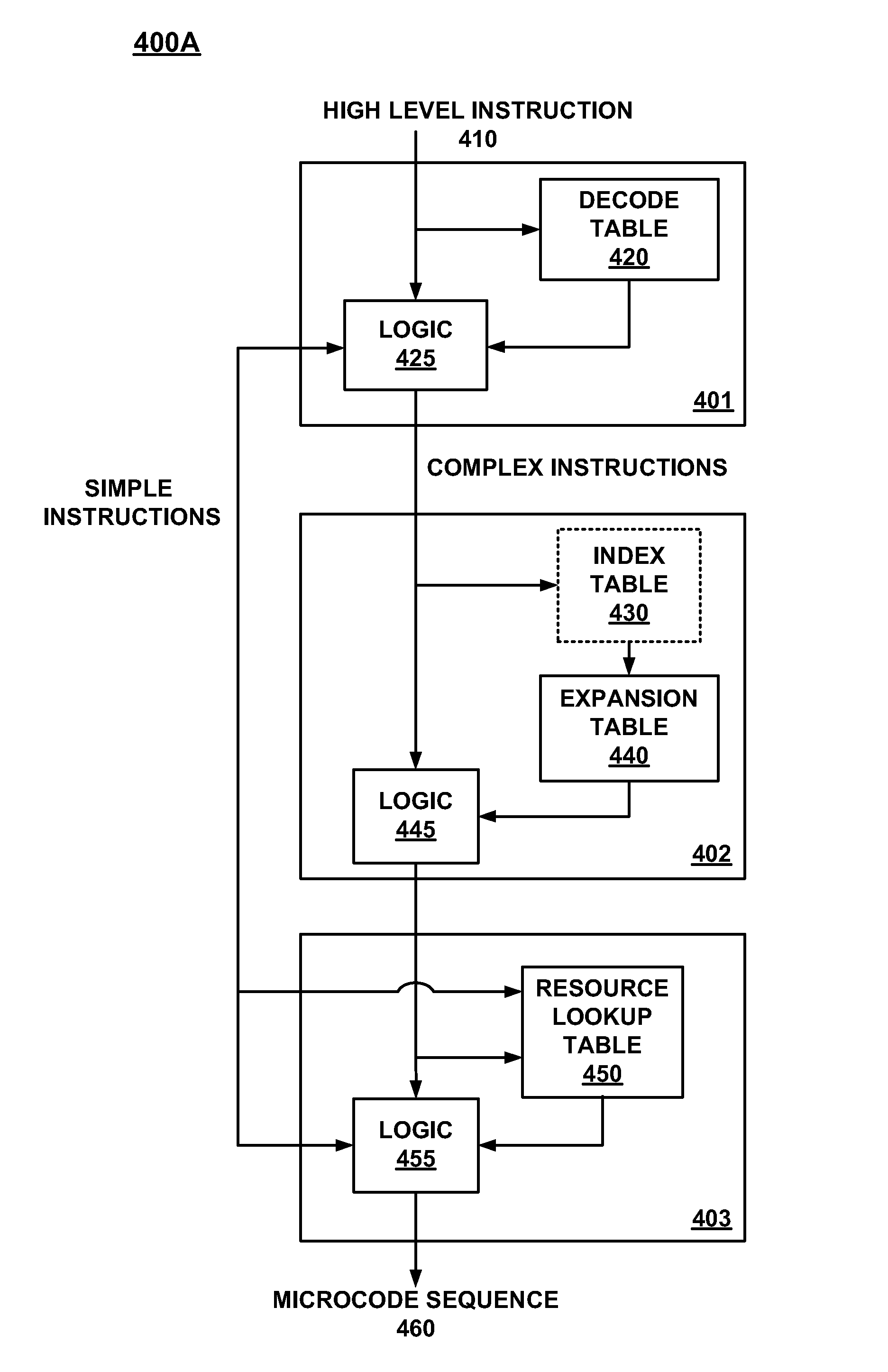
[0013]In another embodiment, a method for patching instructions in a graphics pipeline is disclosed. Specifically, addresses within each of the decode, expansion and resource tables can be patched to modify existing instructions and create new instructions. That is, contents in each address in the tables that are tagged can be replaced with a patch value of a corresponding register. In particular, an address is accessed in one of the patchable lookup tables (e.g., decode, expansion, and resource tables). The contents of the address provide execution information that is associated with the high level instruction. In addition, the address is compared to a list of tagged addresses to determine if the address is tagged for patching. If the address is tagged for patching, an associated register is accessed to read a patch value. The patch value is selected as a replacement for the content of the address in the lookup table, implemented in read only memory (ROM), and is used for further processing of the high level instruction. The ROM lookup table, though hardwired, is a highly efficient implementation of a lookup table, as opposed to random access memory (RAM) which is significantly larger in area and has longer latency.
[0015]In its various embodiments, the present invention can significantly expand the functionality of the scheduling process of a shader by providing high level instructions that can be modified or newly created through a multistage scheduling process that is implemented with patchable ROM, memory, e.g., lookup tables.

Problems solved by technology

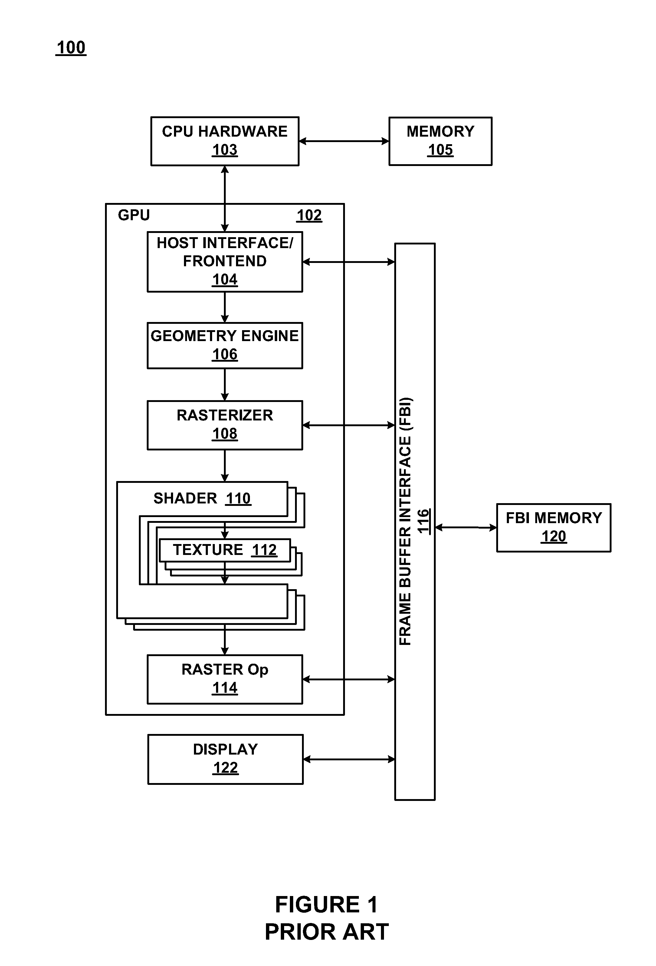
A particular issue in the GPU processing unit of FIG. 1 is that the scheduling of high level instructions (operational codes) in the shader 110 is inflexibly hard coded into the chip platform that contains the GPU processing unit 102.
However, errors within the scheduling process are difficult to repair.
Moreover, modifications to the scheduling process generally cannot be made.
As a result, performance within the shader 110 suffers because of the limitations introduced by errors in the scheduling process.

Method used


Image

  • Method and system for patching instructions in a shader for a 3-D graphics pipeline
  • Method and system for patching instructions in a shader for a 3-D graphics pipeline
  • Method and system for patching instructions in a shader for a 3-D graphics pipeline

Examples


Embodiment Construction

[0024]Reference will now be made in detail to the preferred embodiments of the present invention, examples of which are illustrated in the accompanying drawings. While the invention will be described in conjunction with the preferred embodiments, it will be understood that they are not intended to limit the invention to these embodiments. On the contrary, the invention is intended to cover alternatives, modifications and equivalents, which may be included within the spirit and scope of the invention as defined by the appended claims. Furthermore, in the following detailed description of embodiments of the present invention, numerous specific details are set forth in order to provide a thorough understanding of the present invention. However, it will be recognized by one of ordinary skill in the art that the present invention may be practiced without these specific details. In other instances, well-known methods, procedures, components, and circuits have not been described in detail ...


PUM


Abstract

A method and system for patching instructions in a 3-D graphics pipeline. Specifically, in one embodiment, instructions to be executed within a scheduling process for a shader pipeline of the 3-D graphics pipeline are patchable. A scheduler includes a decode table, an expansion table, and a resource table that are each patchable. The decode table translates high level instructions to an appropriate microcode sequence. The patchable expansion table expands a high level instruction to a program of microcode if the high level instruction is complex. The resource table assigns the units for executing the microcode. Addresses within each of the tables can be patched to modify existing instructions and create new instructions. That is, contents in each address in the tables that are tagged can be replaced with a patch value of a corresponding register.

Description

FIELD OF THE INVENTION[0001]Embodiments of the present invention relate to graphics processors. More specifically, embodiments of the present invention relate to patching instructions in a graphics pipeline unit.BACKGROUND ART[0002]Graphics processing is an important feature of modern high performance computing systems. In graphic processing, mathematical procedures are implemented to render, or draw, graphic primitives, e.g., a triangle or a rectangle, on a display to produce desired visual images. Real time graphics processing requires high speed processing of graphic primitives to produce visually pleasing moving images.[0003]The rendering of three-dimensional graphical images is of interest in a variety of electronic games and other applications. Rendering is the general term that describes the overall multi-step process of transitioning from a database representation of a three-dimensional object to a two-dimensional projection of the object onto a viewing surface, e.g., comput...

Claims


Application Information

Patent Timeline
Patent Type & Authority Patents(United States)
IPC IPC(8): G06T1/20G06F12/02
CPCG06T15/005
Inventor ROUET, CHRISTIANBASTOS, RUIYUE, LORDSON
Owner NVIDIA CORP
Learn More