Systems and methods for making and using nanoelectrodes

a technology of nanoelectrodes and nanoelectrodes, which is applied in the direction of electrostatic separators, diaphragms, electrolysis, etc., can solve the problems of limited electric field gradients, difficult separation of conducting electrodes, and only lithographically created electrodes for research purposes

Active Publication Date: 2010-12-28
RGT UNIV OF CALIFORNIA
View PDF1 Cites 7 Cited by
  • Summary
  • Abstract
  • Description
  • Claims
  • Application Information

AI Technical Summary

Problems solved by technology

To date, however, DEP research has only been performed with lithographically created electrodes having feature sizes that limit the attainable electric field gradients.
The first is the difficulty in preparing conducting electrodes separated by a distance which matches the length of the relevant molecule.
The second is the difficulty in electrically contacting single molecules with sufficient conductivity.
Similar drawbacks are associated with the work of M. Reed et al.
A key challenge in the application of these devices in massively parallel integrated circuits lies in their manufacturability.
In particular, preceding technologies have been unable to control the spatial location of nanowires on a chip with nanometer resolution.
While a significant first step, this method does not achieve resolution on the placement of nanotubes beyond the limits of lithography.
Additionally, the direction in which the nanotubes grow is difficult to control.
While appropriate for research applications, this technique results in nanowires at random locations on a chip.
Additionally, there may be significant boundary resistance if the functional groups (e.g. COOH, NH2 moieties) are not conducting.

Method used


Image

  • Systems and methods for making and using nanoelectrodes
  • Systems and methods for making and using nanoelectrodes
  • Systems and methods for making and using nanoelectrodes

Examples


Embodiment Construction

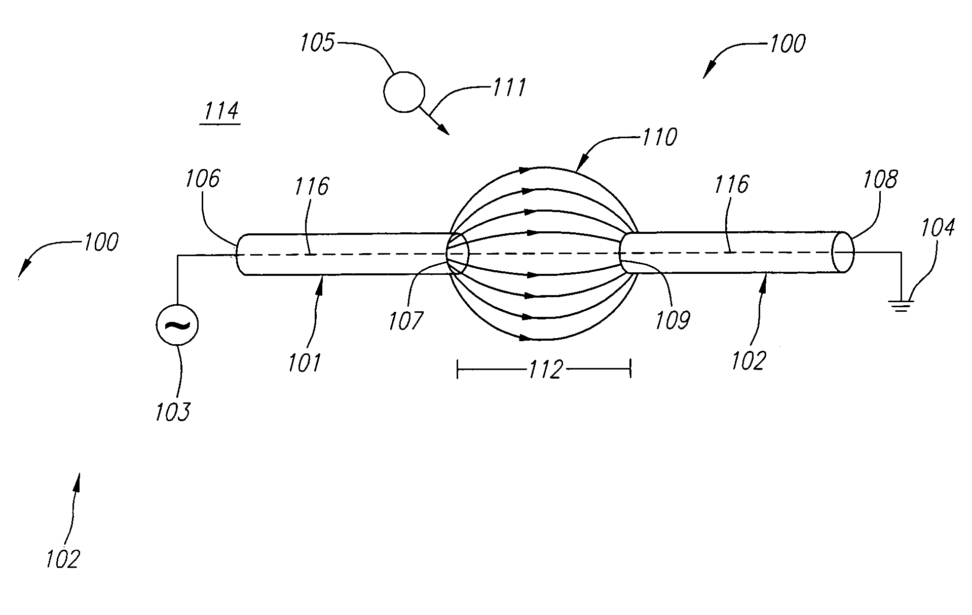
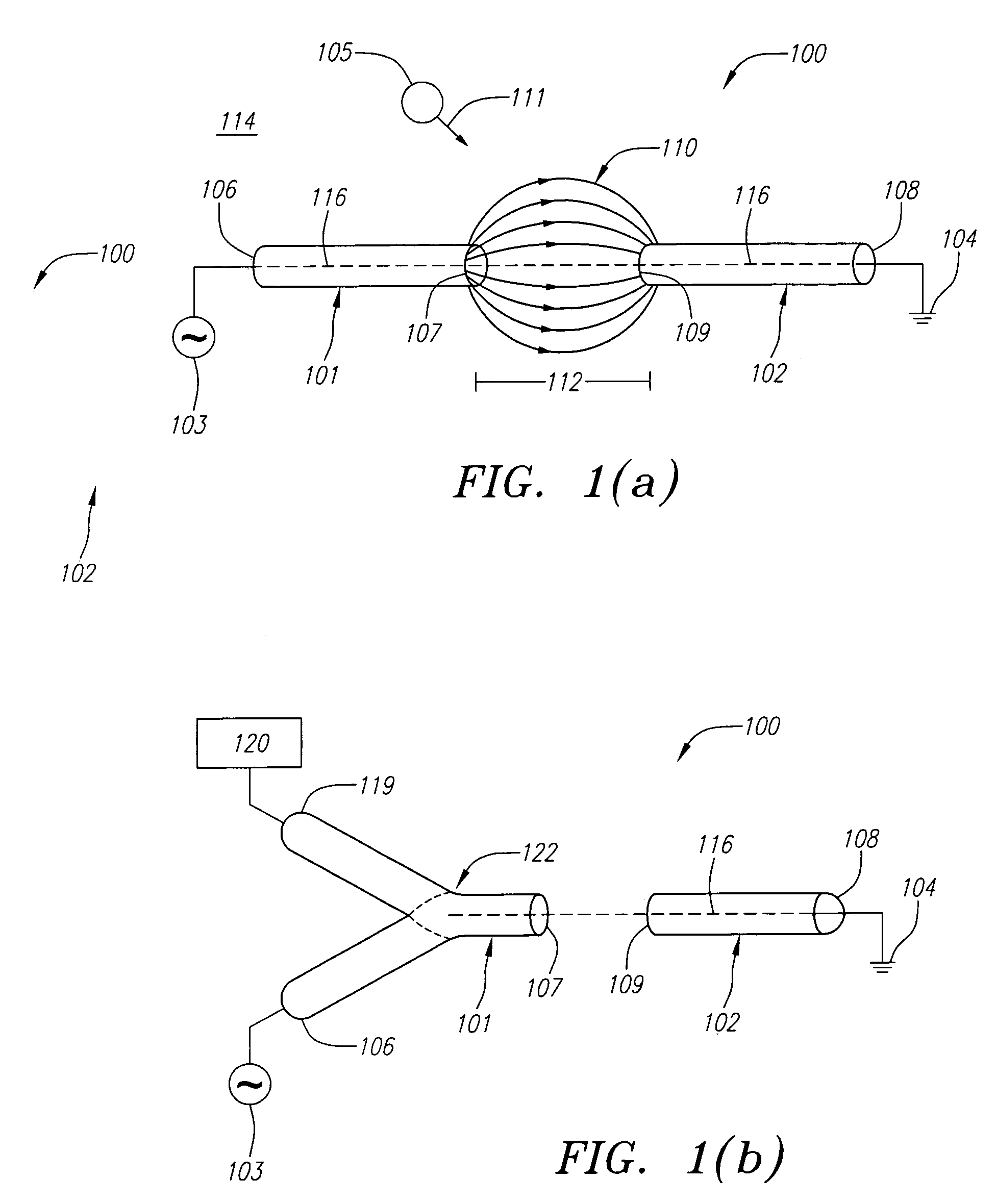
[0024]The present invention provides systems and methods for making and using nanoelectrodes for the dielectrophoretic manipulation of polarizable objects. FIG. 1(a) depicts a nanoelectrode dielectrophoretic system 100, which is a preferred embodiment of the systems and methods described herein. The system 100 includes first and second elongated nanoelectrodes 101 and 102, which are electrically coupled with a first time-varying voltage source 103 and a second voltage source 104, respectively.

[0025]During operation, the voltage sources 103 and 104 apply a time-varying electric potential to the nanotubes 101 and 102 to create a time-varying electric field 110 between the two nanotubes 101 and 102. This electric field 110 induces a dipole moment on a polarizable object 105, which then, in the presence of a field gradient, experiences a dielectrophoretic force 111 that is sufficient to overcome the thermal Brownian motion and cause the object 105 to move. Preferably, the object 105 is ...


PUM

PropertyMeasurementUnit
lengthaaaaaaaaaa
lengthaaaaaaaaaa
sizeaaaaaaaaaa

Abstract

Systems and methods are provided for the manipulation of a polarizable object with a pair of elongated nanoelectrodes using dielectrophoresis. The nanoelectrodes can be carbon nanotubes and are coupled with one or more time-varying voltage sources to create an electric field gradient in a gap between the nanotubes. The gradient induces the movement of a polarizable object in proximity with the field. The nanotube pair can be used to trap a single polarizable object in the gap. A method of fabricating a nanoelectrode dielectrophoretic system is also provided. Applications extend to self-fabricating nanoelectronics, nanomachines, nanochemistry and nanobiochemistry. A nanoelectrode dielectrophoretic system having an extended nanoelectrode for use in applications including the self-fabrication of a nanowire, as well as methods for fabricating the same, are also provided.

Description

CROSS-REFERENCE TO RELATED APPLICATIONS[0001]This application claims priority to provisional application Ser. No. 60 / 450,985 filed Feb. 27, 2003, which is fully incorporated by reference herein.[0002]This invention was made with Government support under Grant No. DAAD19-02-1-0387, awarded by the Army. The Government has certain rights in this invention.FIELD OF THE INVENTION[0003]This invention relates to systems and methods for making and using nanoelectrodes for the manipulation of nano-scale polarizable objects for applications in molecular electronics, electronically assisted chemical self-assembly, nanomanufacturing, nano-biotechnology, and the like.BACKGROUND OF THE INVENTION[0004]Dielectrophoresis (DEP) is a technique that employs time-varying, or alternating current (AC) electric fields to apply a force to polarizable objects. The force relies on the difference in the polarizability of the system compared to its surrounding media (e.g. water) to manipulate not only charged o...

Claims


Application Information

Patent Timeline
Patent Type & Authority Patents(United States)
IPC IPC(8): B03C5/02G01Q70/12G01Q90/00
CPCB03C5/026B82Y30/00B82Y10/00
Inventor BURKE, PETER J.LI, SHENGDONGZHENG, LIFENG
Owner RGT UNIV OF CALIFORNIA
Why Eureka
Try Eureka