Power unit

a power unit and power technology, applied in the direction of motor/generator/converter stopper, motor/generator/converter stopper, etc., can solve the problems of increasing the size of the second rotating machine, increasing the weight and manufacturing costs, and preventing the attainment of sufficient power generation efficiency, etc., to reduce the power transmission loss in the transmission, improve driving efficiency, and suppress the effect of speed change shock

Inactive Publication Date: 2011-01-04
HONDA MOTOR CO LTD
View PDF18 Cites 7 Cited by
  • Summary
  • Abstract
  • Description
  • Claims
  • Application Information

AI Technical Summary

Benefits of technology

[0024]As is clear from the above construction, it is possible to distribute the power of the prime mover to the front wheel and the rear wheel, and drive the both simultaneously, whereby it is possible to realize an all-wheel drive vehicle. In addition, in driving the whole wheels including the front wheel and the rear wheel of the vehicle as the driven part, it is possible to obtain the same advantageous effects as described hereinabove.
[0025]Preferably, the transmission is a gear-type stepped transmission including a plurality of gear trains which are different in gear ratio from each other, and outputs power input thereto after changing a speed of the power by one of the gear trains.
[0026]With the arrangement of this preferred embodiment, since the transmission is a gear-type stepped transmission, compared with the case of a belt-type stepless transmission, it is possible to reduce the power transmission loss in the transmission. Therefore, it is possible to further improve the driving efficiency. On the other hand, when the prime mover is connected to the driven part including the other wheel via the gear-type stepped transmission, during the speed-changing operation, before connection of a gear train is established for a shift to a desired transmission gear ratio, the torque of the prime mover is not transmitted, and a speed change shock, such as a sudden decrease in the torque caused thereby, can occur. According to the present embodiment, the second rotating machine is connected to the driven part without via the transmission, and hence during the speed-changing operation of the transmission, it is possible to transmit the torque of the second rotating machine to the driven part, which makes it possible to suppress the speed change shock.

Problems solved by technology

For the same reason, the second rotating machine is increased in size to increase its weight and manufacturing costs.
Further, since the induction machine is formed by the stator and the intermediate rotor, when the electric power is generated by the first stator, Joule heat is generated not only in the coil of the first stator but also in the coil of the intermediate rotor, which prevents the sufficient power generation efficiency from being obtained, to further lower the driving efficiency of the power unit.
Further, since the intermediate rotor is formed by winding coil around the iron core, the durability of the intermediate rotor is relatively low, and in turn, the durability of the whole power unit is also low.
Further, there is a fear that the intermediate rotor, which is so low in durability, cannot withstand the repeated transmission of the power from the engine connected thereto, and becomes incapable of properly transmitting the power to the drive wheels.

Method used


Image

  • Power unit
  • Power unit
  • Power unit

Examples


first embodiment

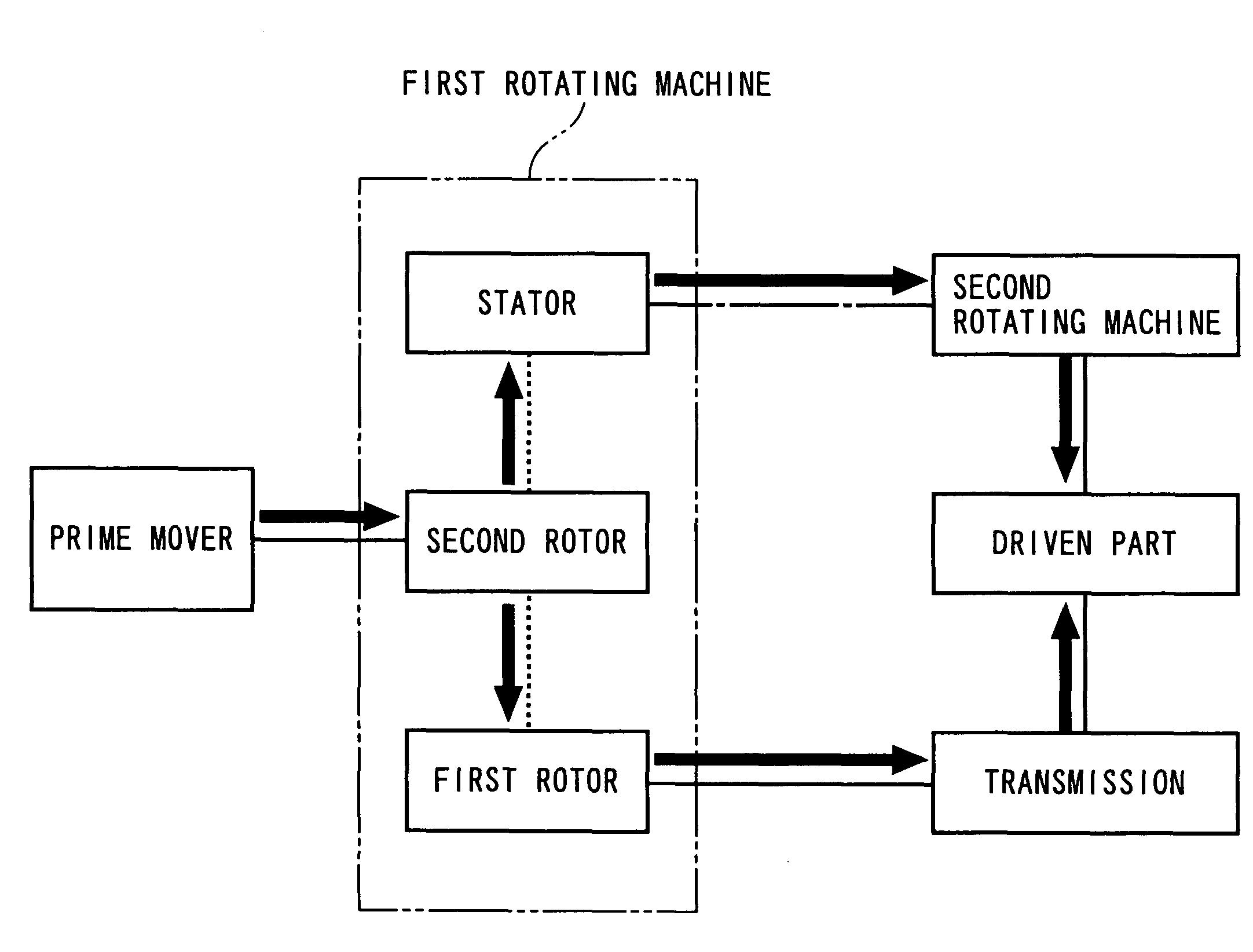
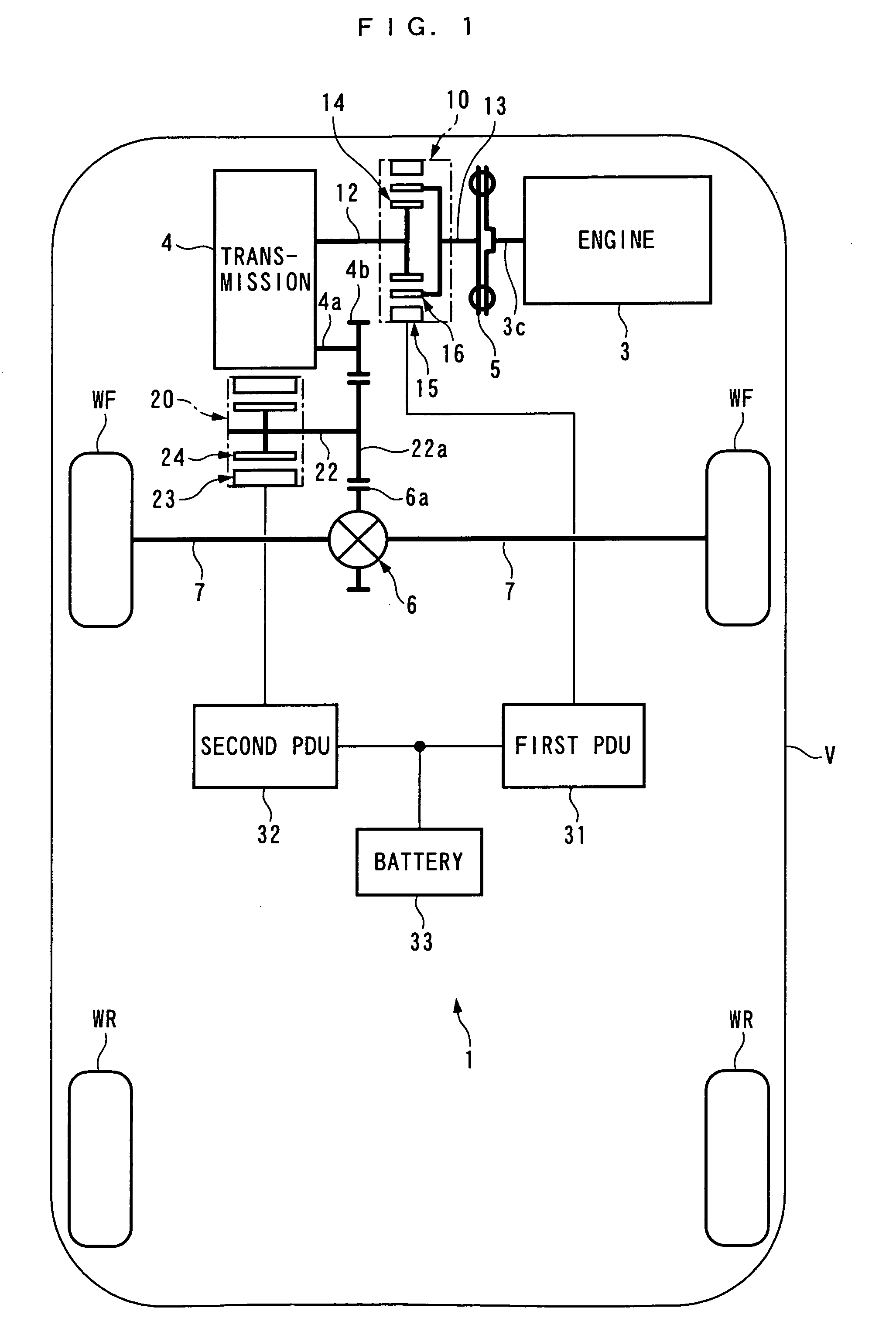
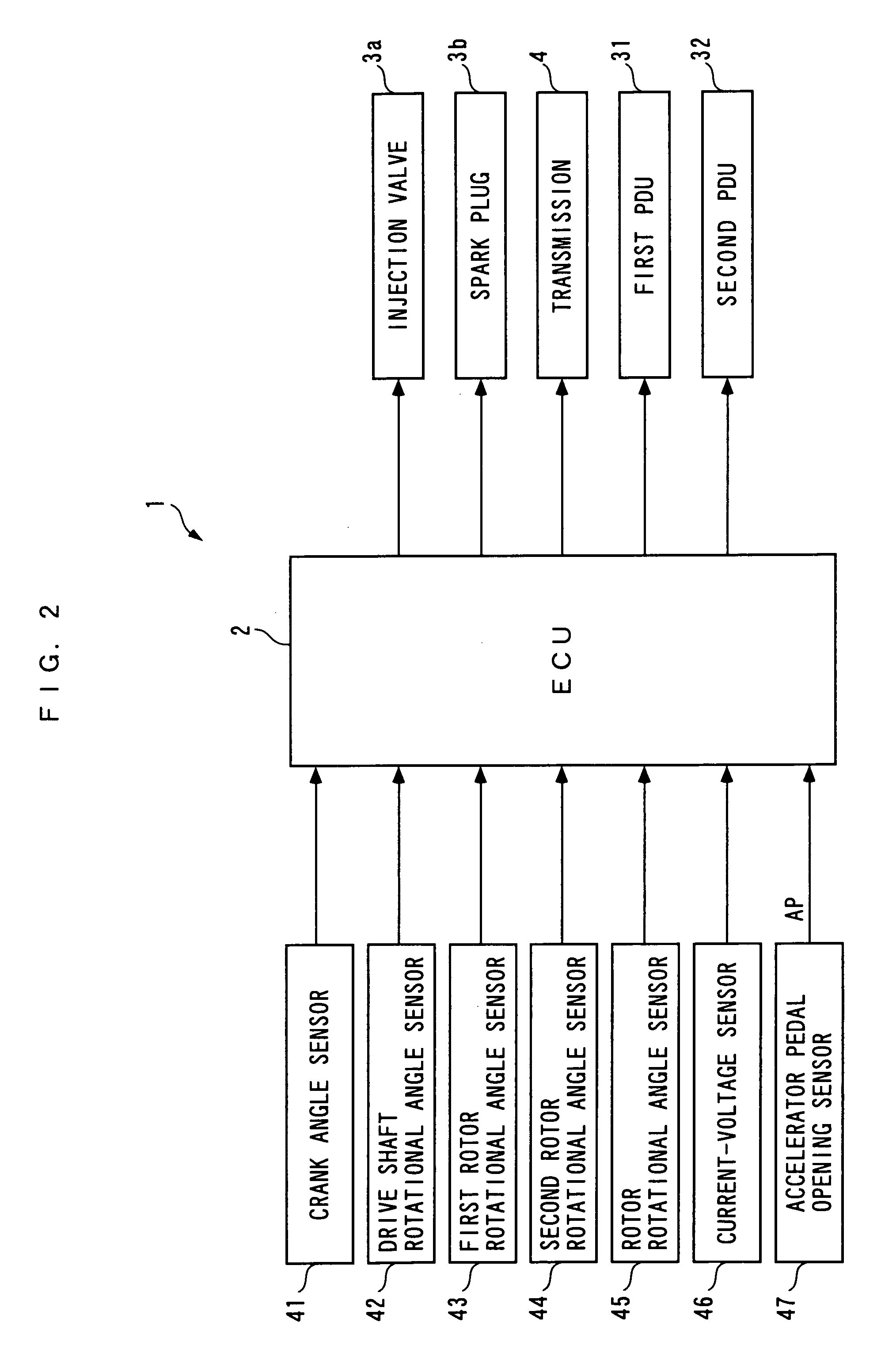
[0051]The invention will now be described in detail with reference to the drawings showing preferred embodiments thereof. FIG. 1 schematically shows a vehicle V on which a power unit 1 according to the present invention is installed. The vehicle V is a four-wheel vehicle having left and right front wheels WF, WF and left and right rear wheels WR, WR. It should be noted that in the following description, the left side and the right side as viewed in FIG. 1 will be referred to as “left” and “right”. This power unit 1 is for driving left and right front wheels WF, WF of the vehicle V, and is provided with an internal combustion engine 3, a first rotating machine 10, and a second rotating machine 20, which are power sources, a transmission 4, a differential gear mechanism 6, and left and right drive shafts 7, 7 for transmitting driving force to the forward wheels WF, WF, and an ECU 2 for controlling the respective operations of the internal combustion engine 3, the transmission 4, and t...

second embodiment

[0150]Although in the second embodiment, the transmission 4 is connected to the front wheels WF, WF and the second rotating machine 20 is connected to the rear wheels WR, WR, inversely, the transmission 4 may be connected to the rear wheels WR, WR, and the second rotating machine 20 to the front wheels WF, WF.

[0151]Further, the present invention is by no means limited to the above-described embodiment, but can be practiced in various forms. For example, although in the embodiments, the transmission 4 having the speed positions of the first to third speeds is described by way of example, the number of speed positions is not limited to this, but it is to be understood that any suitable number of speed positions may be employed. This also applies to transmission gear ratio of each of the speed positions. Further, although in the embodiments, the gear-type stepped transmission is employed as the transmission 4, a belt-type or a toroidal-type stepless transmission may be employed. Furthe...


PUM


Abstract

A power unit which makes it possible to reduce power transmitted from a prime mover to a driven part via an electrical path, to thereby increase the efficiency of driving the driven part. A first rotating machine of the power unit inputs and outputs energy between a stator and first and second rotors thereof, via magnetic circuits formed by generation of a rotating magnetic field, and the rotating magnetic field, and the rotors rotate while maintaining a linear relation in which respective differences in rotational speed between the rotating magnetic field and the second rotor, and between the second and first rotors are equal. The rotors are mechanically connected to a prime mover and a transmission, respectively. A second rotating machine of the power unit is mechanically connected to a drive part without via the transmission, and electrically connected to the stator.

Description

BACKGROUND OF THE INVENTION[0001]1. Field of the Invention[0002]The present invention relates to a power unit for driving driven parts for propelling a transport machine.[0003]2. Description of the Related Art[0004]Conventionally, as a power unit of this kind, one disclosed e.g. in Japanese Laid-Open Patent Publication (Kokai) No. 2000-197324 is known. This power unit is for driving drive wheels of a vehicle, and is provided with an internal combustion engine, and first and second rotating machines. The first rotating machine has a stator formed by a plurality of armatures, an intermediate rotor formed by winding coil around an iron core, and an inner rotor formed by a permanent magnet. The stator, the intermediate rotor, and the inner rotor are arranged in this order from the outside to the inside in a radial direction. Further, in the first rotating machine, an induction machine is formed by the stator and the intermediate rotor, and a synchronous machine is formed by the intermed...

Claims


Application Information

Patent Timeline
Patent Type & Authority Patents(United States)
IPC IPC(8): B60K6/00H02K23/60B60L11/14B60K6/26B60K6/36B60K6/448B60K6/52B60K6/547B60K17/04B60L50/16H02K7/116H02K7/18H02K16/02
CPCB60K6/20B60K6/448B60K1/02B60K2006/262Y02T10/6243Y02T10/92Y02T10/62
Inventor MORITA, HIDEKIHAMADA, TETSUROU
Owner HONDA MOTOR CO LTD
Why Eureka
Try Eureka