High aspect-ratio X-ray diffractive structure stabilization methods and systems

a technology of diffractive structure and high aspect ratio, applied in the direction of instruments, material analysis using wave/particle radiation, optical elements, etc., can solve the problems of reducing performance, difficult stabilizing nanostructures, and inability to fill the spaces between structures with organic materials, so as to achieve not substantially undermine the diffractive performance

Active Publication Date: 2011-01-04
CARL ZEISS X RAY MICROSCOPY
View PDF5 Cites 33 Cited by
  • Summary
  • Abstract
  • Description
  • Claims
  • Application Information

AI Technical Summary

Benefits of technology

[0005]The present invention concerns stabilizing planar structures, including nanostructures, such as x-ray grating-like diffractive optical elements including gratings and zone plate lenses. These structures are typically made on a flat substrate, and therefore are only fixed at the bottom. At high aspect ratios, the stability can be poor since even electrostatic and van de Waals forces can alter the structure. Embodiments of the present invention involve the use of a top coating, possibly including metallic materials such as titanium, aluminum, or molybdenum, to constrain the nanostructures at the top and at the same time eliminate electrostatic forces, and also reduce any thermal gradients that may be present across the device.
[0008]In the current embodiment, the top layer is used to mechanically stabilize the structures, even when they have aspect ratios in the range of 10-50, and higher. Preferred materials for the top layer include titanium, molybdenum, and / or aluminum. The top layer should be thick enough to provide mechanical stability but thin enough so as to not substantially undermine the diffractive performance; currently the top layer has a thickness of 50-500 nm.

Problems solved by technology

Although there are typically no moving parts in x-ray optical elements, stabilizing the nano-structures is more difficult than in integrated circuits.
For example, filling the spaces between the structures with organic material is not possible because the material would not be stable under prolonged x-ray exposure and filling the spaces with metallic material will affect the differential x-ray absorption properties and consequently reduce the performance.
At high aspect ratios, the stability can be poor since even electrostatic and van de Waals forces can alter the structure.

Method used


Image

  • High aspect-ratio X-ray diffractive structure stabilization methods and systems
  • High aspect-ratio X-ray diffractive structure stabilization methods and systems
  • High aspect-ratio X-ray diffractive structure stabilization methods and systems

Examples


Embodiment Construction

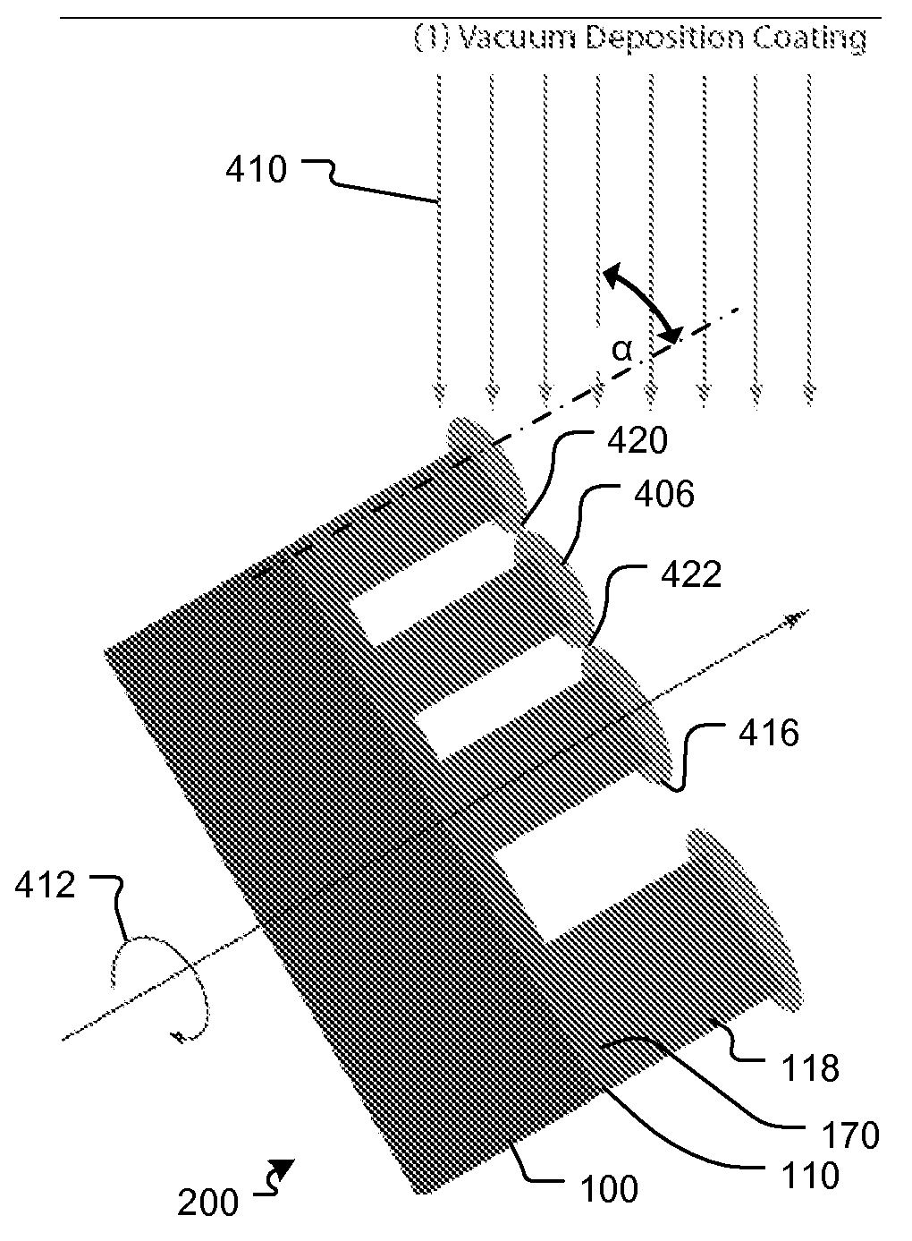
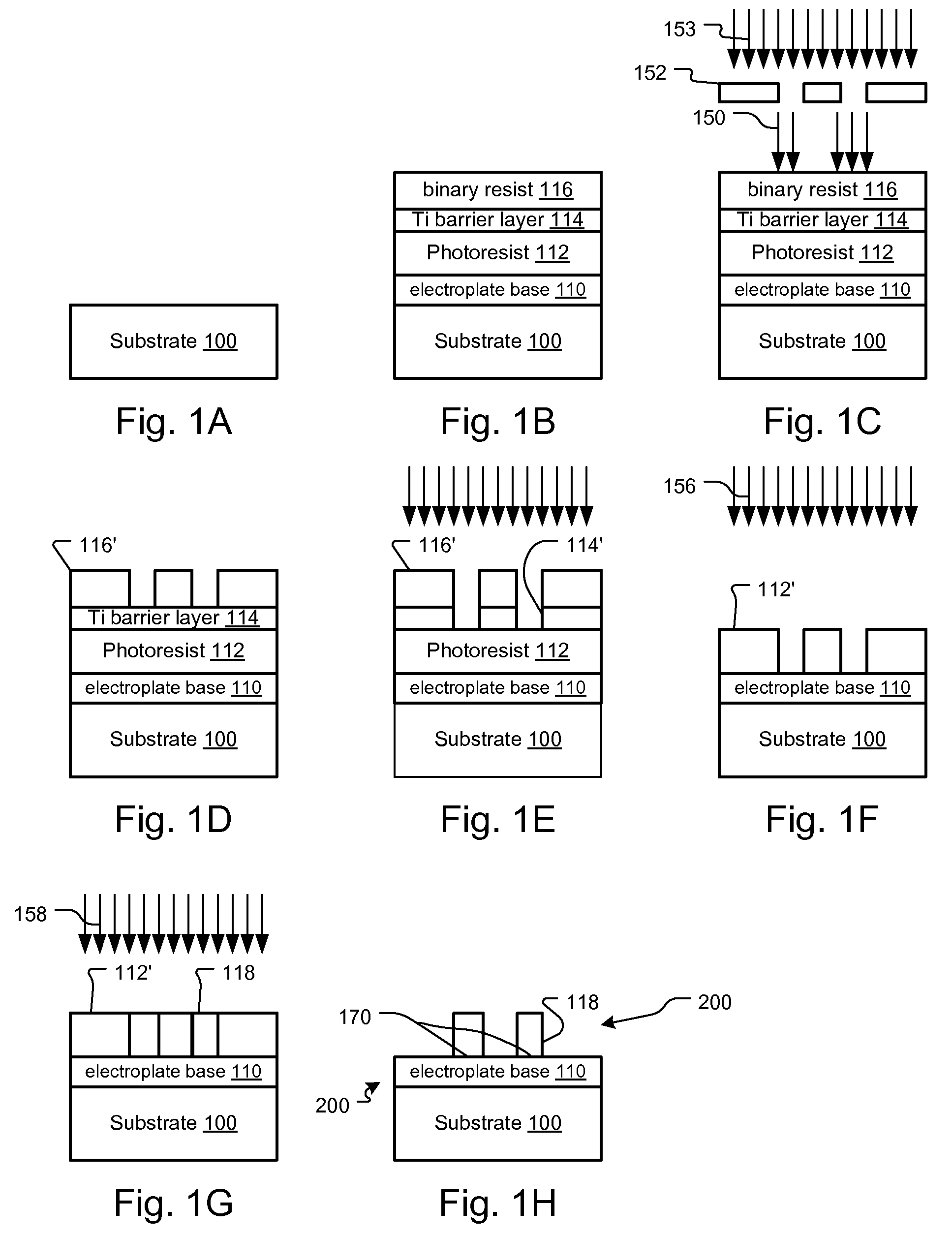
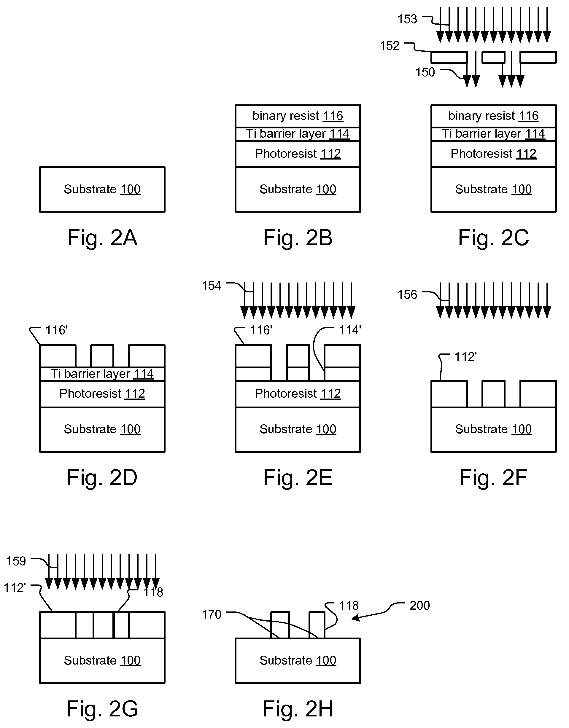
[0019]Gratings and zone plates are diffractive elements that manipulate light by the principle of diffraction. With x-ray radiation in the range of 100 eV and 10 keV, most materials provide little refractive effect but become very absorptive. As a consequence, diffractive optical elements have become the most effective means of changing the direction of and focusing x-ray beams. These diffractive optical elements are typically fabricated lithographically, with processes similar to that used in the fabrication of microelectromechanical systems (MEMS) and semiconductor integrated circuits. Two types of processes are often used today: 1. electroplating process shown in FIGS. 1A-1H; and a lift-off method shown in FIGS. 2A-2H.

[0020]FIGS. 1A-1H show an exemplary electroplating process for diffractive x-ray optics fabrication.

[0021]A substrate 100 is first coated with a conducting material that functions as an electroplate base 110, as illustrated in FIGS. 1A and 1B. Typically the conducti...


PUM


Abstract

A method to stabilize planar nanostructures, for example grating and zone plate lenses that are typically used for directing or focusing x-ray radiation, includes the deposition of a top, stabilizing layer. The structures are typically made on a flat substrate, and therefore are only fixed at the bottom. At high aspect ratio, the stability can be poor since small forces such as electrostatic forces and van de Waals forces that are often present can alter the structure. The top coating of a metallic material such as titanium constrains the nanostructures at the top and at the same time eliminates electrostatic forces and reduces any thermal gradient that may be present across the device.

Description

BACKGROUND OF THE INVENTION[0001]High-aspect ratio nanostructures with widths between 10 nanometers (nm) and several micrometers and a height-to-width ratio in the range of 5-100 are becoming more widely used in many fields such as micro-electronics, nanotechnology, and diffractive optics. Like tiny sky-scrapers (e.g. Sear's Tower has an aspect ratio of roughly 15), stabilization of these thin and tall structures is a major engineering hurdle. An important challenge in producing these nanostructures is developing methods to enhance their stability without compromising their performance. This can sometimes be done easily, particularly in systems with no moving parts, such as semiconductor integrated circuits, but is often difficult in most other applications.[0002]Because of the wavelengths involved, diffractive x-ray optics presents some of the greatest challenges. Two examples are gratings and zone plate lenses. These optical elements include repeating structures that block or phas...

Claims


Application Information

Patent Timeline
Patent Type & Authority Patents(United States)
IPC IPC(8): G02B5/18
CPCG02B5/1857G02B5/1876G21K1/06
Inventor YUN, WENBINGLYON, ALAN FRANCISFENG, YAN
Owner CARL ZEISS X RAY MICROSCOPY
Why Eureka
Try Eureka