PCVD apparatus with a choke defined within a microwave applicator

a technology of microwave applicator and pcvd apparatus, which is applied in the direction of optical elements, manufacturing tools, instruments, etc., can solve the problems of inefficient energy consumption, interference with the operation of electronic equipment present in the vicinity, and increasing the problem of high-frequency power leakage, so as to achieve the maximum concentration of high-frequency energy and minimise the problem of high-frequency energy leakage

Active Publication Date: 2011-01-11
DRAKA FIBRE TECH BV
View PDF17 Cites 2 Cited by
  • Summary
  • Abstract
  • Description
  • Claims
  • Application Information

AI Technical Summary

Benefits of technology

[0005]The object of the present invention is thus to provide an apparatus and a method for carrying out a PCVD deposition process wherein power levels upwards of 2.5 kW can suitably be used without any of the aforesaid drawbacks occurring.
[0038]In a special embodiment, the inner wall of the furnace may furthermore be provided with a layer that absorbs microwave radiation, for example a layer of siliciumcarbide (SiC). The thickness of such a layer is preferable in agreement with λ / 4 (at a certain geometry and refractive index of said material). An additional advantage of such a construction is that the microwave radiation is converted into heat, as a result of which less energy needs to be supplied to the furnace.

Problems solved by technology

The present inventors have found that leakage of high-frequency power becomes increasingly problematic when high-frequency power levels upwards of about 2.5 kW are used.
The consequence of such leakage is an inefficient energy consumption.
In addition, ambient radiation usually occurs, which may interfere with the operation of electronic equipment present in the vicinity thereof.
In addition to that, the leakage of radiation to operating staff is undesirable for medical reasons.
The present inventors have furthermore found that such leakage of high-frequency energy may result in the formation of a standing wave in the substrate tube, leading to a risk that a sinusoidal disruption in the deposition of the vitreous layers along the length of the substrate tube will occur, which is undesirable.

Method used


Image

  • PCVD apparatus with a choke defined within a microwave applicator
  • PCVD apparatus with a choke defined within a microwave applicator
  • PCVD apparatus with a choke defined within a microwave applicator

Examples


Embodiment Construction

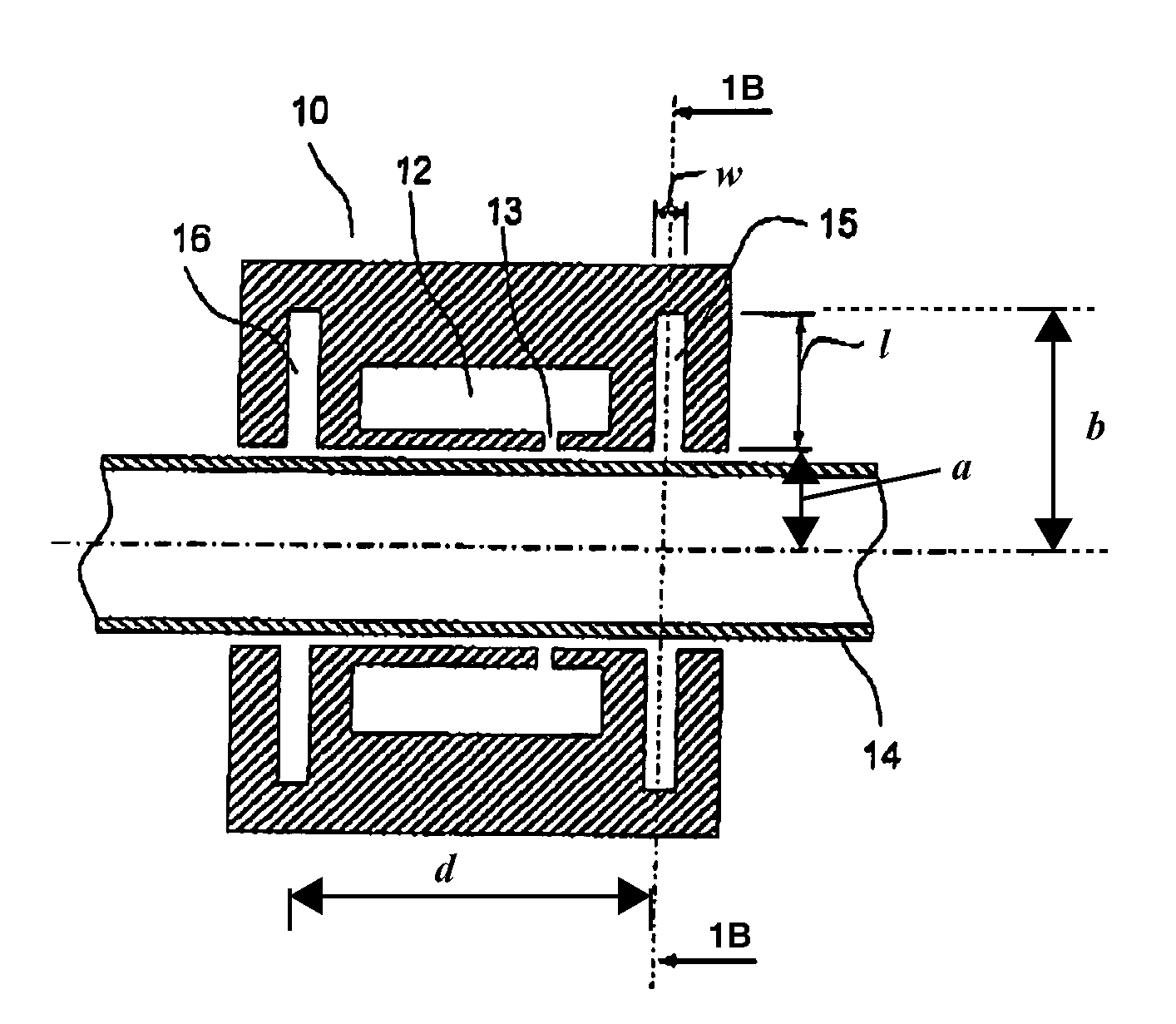
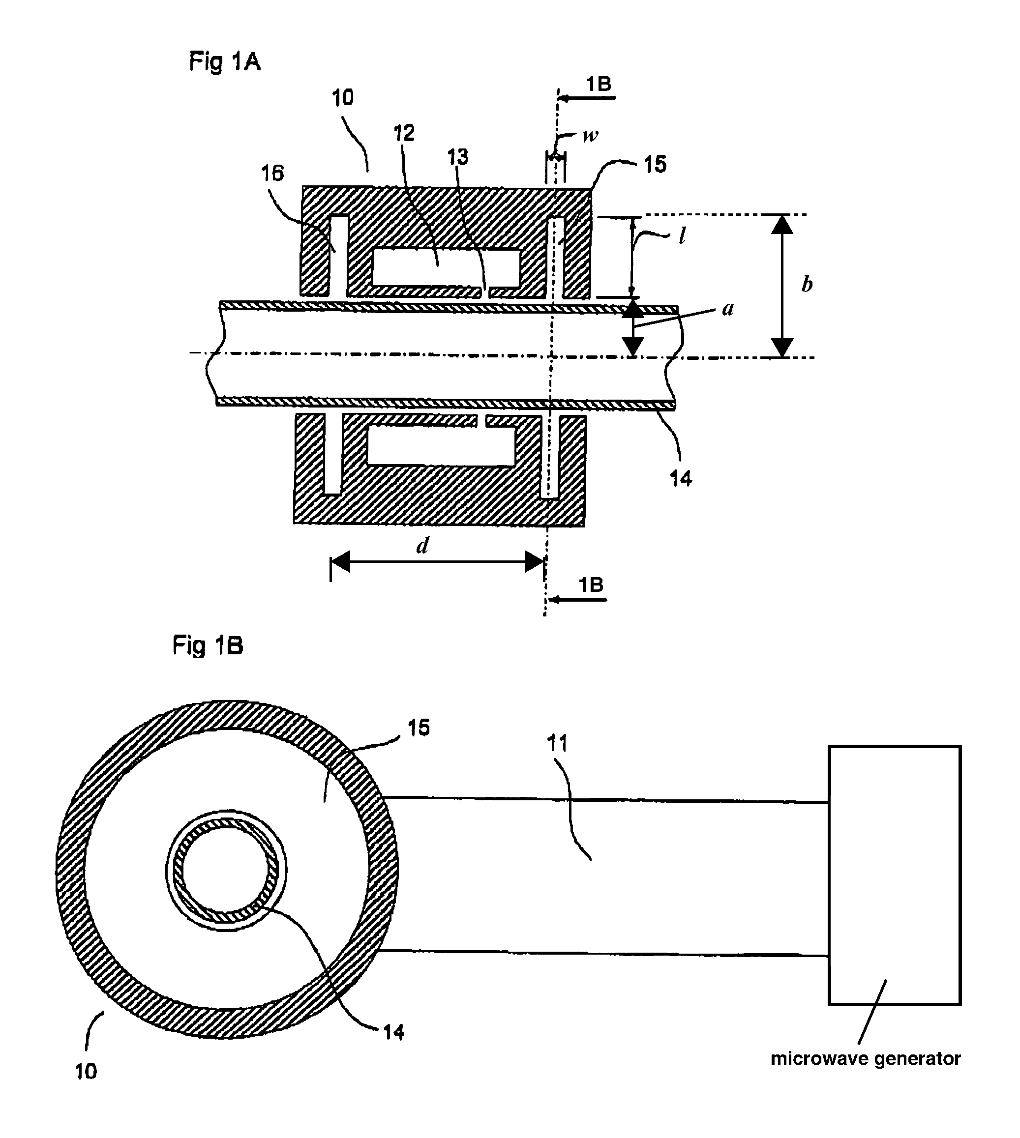
[0046]FIGS. 1A and 1B show an example of an applicator as used in the present PCVD process. Microwaves from a microwave generator are carried to an applicator 10 via a waveguide 11. Via a resonator cavity 12 and a slit 13 in the applicator, the high-frequency energy from the microwaves is coupled into a plasma which is present in the substrate tube 14 near the resonator cavity 12. Present in the applicator are chokes 15, 16, which prevent leakage of high-frequency energy. By using a length l for the chokes smaller than the quarter-wavelength, the effect of the choke is optimised. For practical reasons, the width w of a choke is usually selected to be smaller than the length l or the choke and larger than about 3 mm. If two separate chokes 15, 16 are used, as is shown in FIG. 1A, the spacing d between the two chokes 15, 16 is maximally λ.

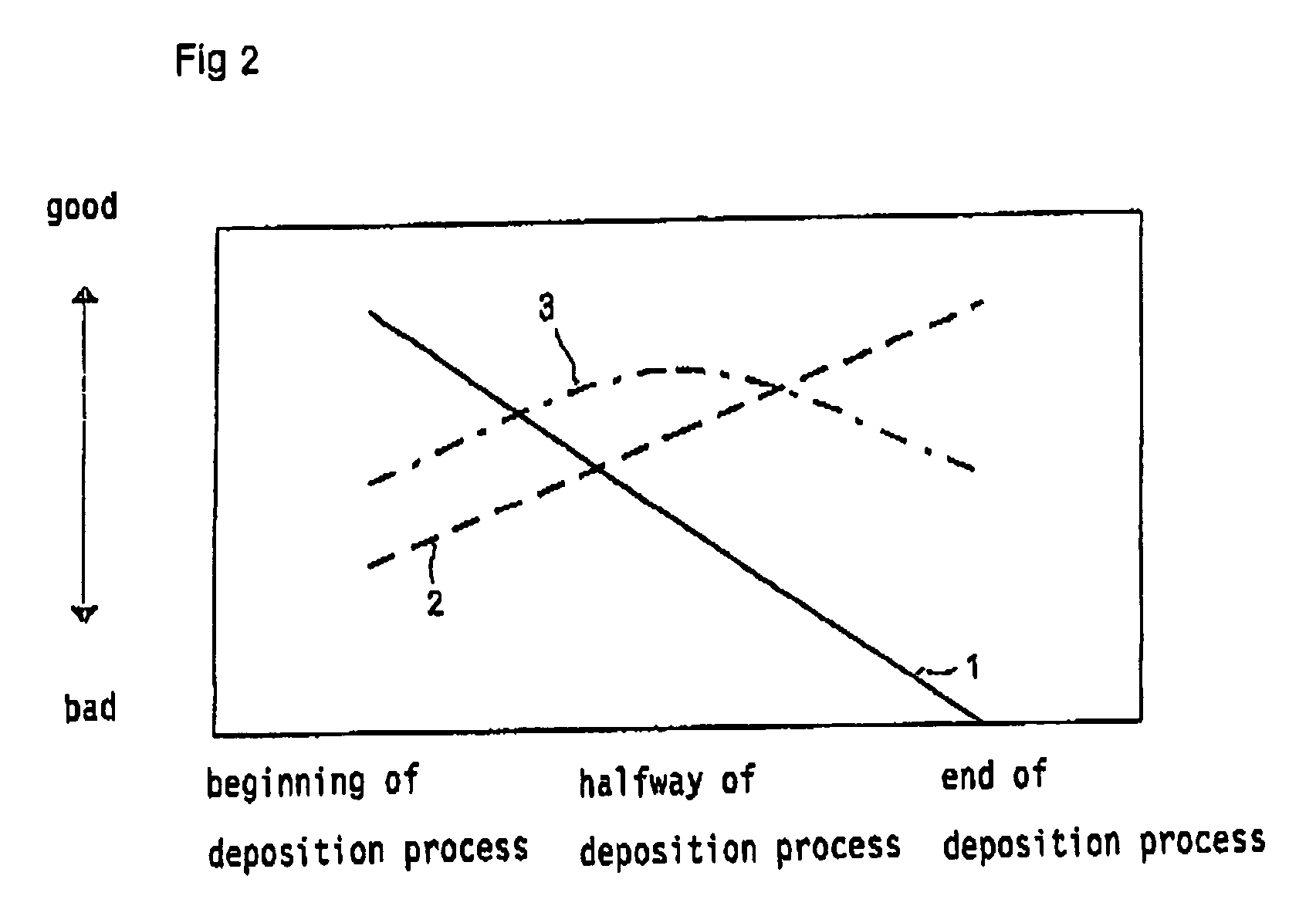
[0047]FIG. 2 shows the effect of chokes of different length l during the deposition of layers on the inner wall of a glass substrate tube. The full ...


PUM

PropertyMeasurementUnit
Angleaaaaaaaaaa
Lengthaaaaaaaaaa
Volumeaaaaaaaaaa

Abstract

The present invention relates to an apparatus for carrying out a PCVD deposition process, wherein one or more doped or undoped layers are coated onto the interior of a glass substrate tube, which apparatus comprises an applicator having an inner and an outer wall and a microwave guide which opens into the applicator, which applicator extends around a cylindrical axis and which is provided with a passage adjacent to the inner wall, through which the microwaves can exit, over which cylindrical axis the substrate tube can be positioned, and wherein at least one choke of annular shape having a length l and a width w is centred around the cylindrical axis within the applicator.

Description

FIELD OF THE INVENTION[0001]The present invention relates to an apparatus for carrying out a PCVD deposition process, wherein one or more doped or undoped layers are deposited onto the interior of a glass substrate tube, which apparatus comprises an applicator having an inner and an outer wall and a microwave guide which opens into the applicator, which applicator extends around a cylindrical axis and which is provided with a passage adjacent to the inner wall, through which the microwaves can exit, over which cylindrical axis the substrate tube can be positioned, and wherein at least one choke of annular shape having a length l and a width w is centred around the cylindrical axis within the applicator. The present invention furthermore relates to a method of manufacturing a preform, which method comprises carrying out a PCVD deposition process for the purpose of depositing one or more doped or undoped layers onto the interior of a glass substrate tube and subsequently thermally col...

Claims


Application Information

Patent Timeline
IPC IPC(8): C03B37/018C23C16/04G02B6/00C23C16/50C23C16/511H01J37/32H05H1/46
CPCC03B37/0183Y02P40/57C23C16/50
Inventor VAN STRALEN, MATTHEUS JACOBUS NICOLAASDECKERS, ROB HUBERTUS MATHEUS
Owner DRAKA FIBRE TECH BV
Why Eureka
Try Eureka