Noise dampener hub assembly for a circular saw

Active Publication Date: 2011-01-11
HARRIS GRACE ELIZABETH
View PDF34 Cites 11 Cited by
  • Summary
  • Abstract
  • Description
  • Claims
  • Application Information

AI Technical Summary

Benefits of technology

[0006]It is also an object of the invention to produce a novel noise dampener

Problems solved by technology

An operator mounting a blade backwards is a very common problem.
Most blade manufacturers include a direction arrow on the blade core, but it is often small and difficult to see.
Also

Method used


Image

  • Noise dampener hub assembly for a circular saw
  • Noise dampener hub assembly for a circular saw
  • Noise dampener hub assembly for a circular saw

Examples


Embodiment Construction

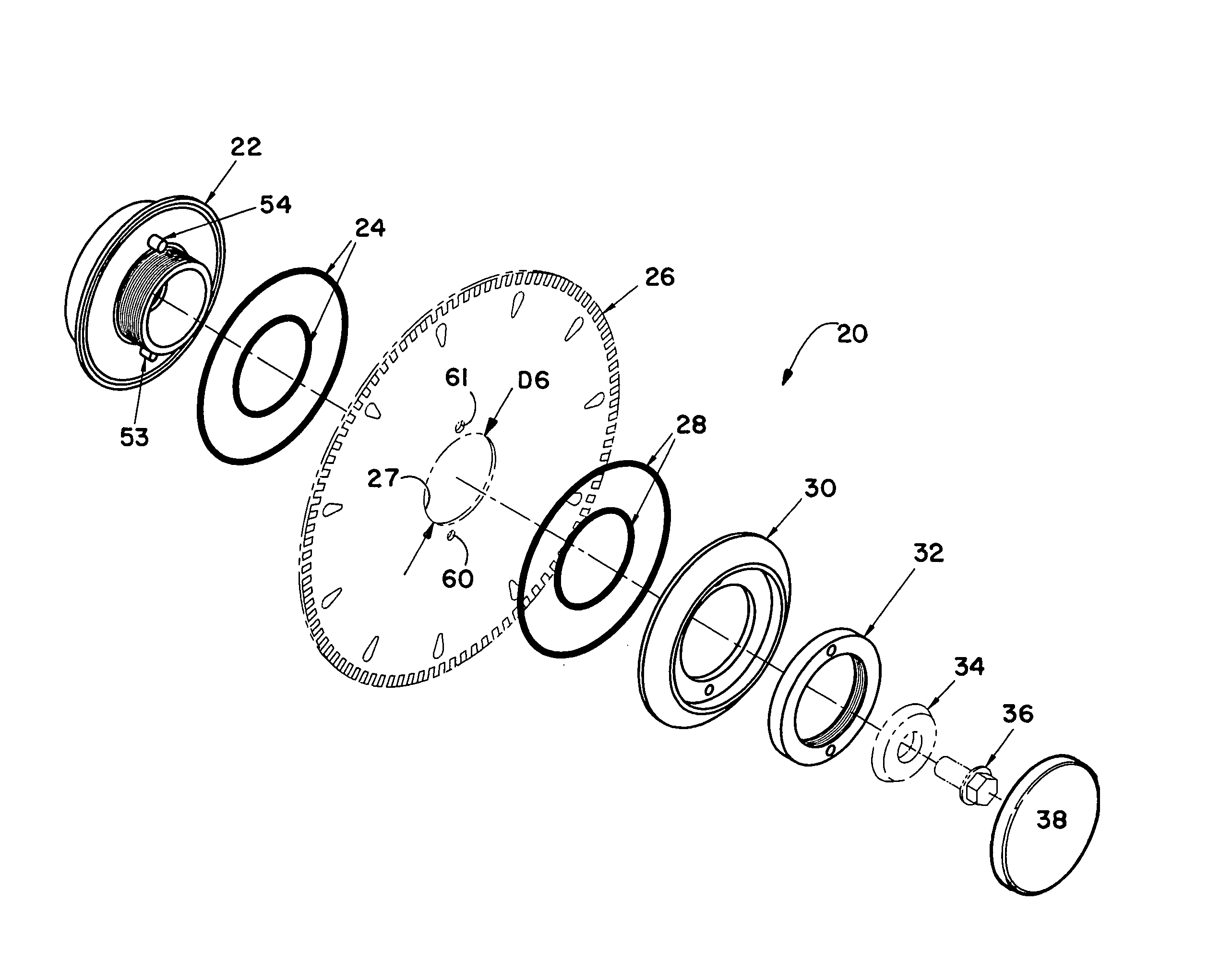
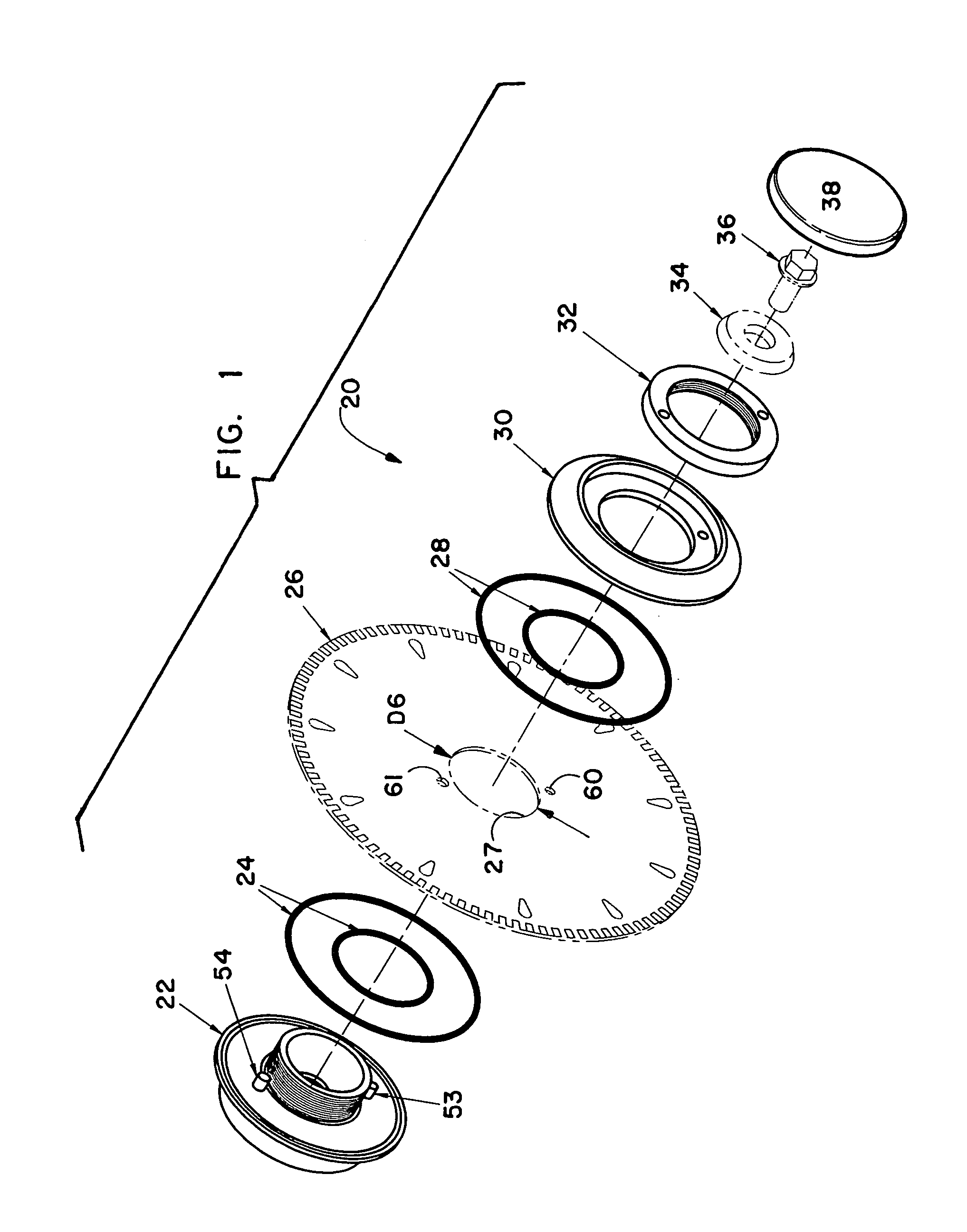
[0030]A noise dampener hub assembly for mounting a circular blade on the drive shaft of a circular saw is generally designated numeral 20. It is illustrated in FIGS. 1-8 of the drawings. The noise dampener hub assembly is illustrated in FIG. 1 in an exploded front perspective view. It has a spindle hub 22, a pair of radially spaced O-rings 24, a circular saw blade 26, (having a bore hole 27 having a diameter D6) a pair of radially spaced O-rings 28, an outside noise dampener disc member 30, a spanner hub 32, a splined washer 34, a bolt 36, and a cover cap 38.

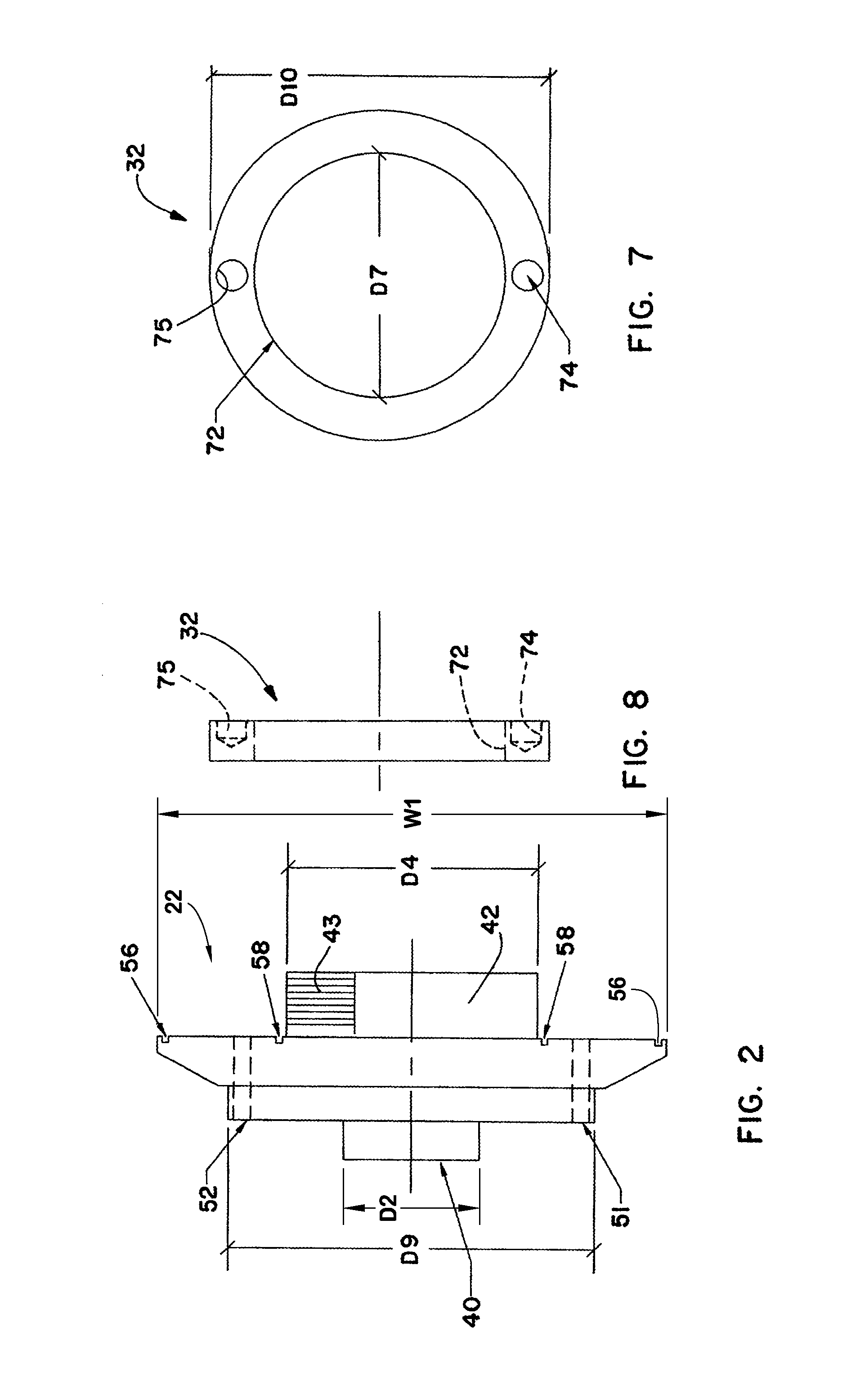
[0031]Spindle hub 22 is best understood by referring to FIGS. 2-4. It has a tubular sleeve member 40 having an inside diameter D1 and an outside diameter D2. It also has a tubular hub member 42 having an inside diameter D3 and an outside diameter D4. It has external lefthand threads 43. Spindle hub 22 also has an inner noise dampener disc member 45. Tubular sleeve member 40 is connected at its rear end to the rear end of hub mem...


PUM

PropertyMeasurementUnit
Angleaaaaaaaaaa
Diameteraaaaaaaaaa
Noiseaaaaaaaaaa

Abstract

A noise dampener hub assembly for mounting a circular blade on the drive shaft of a circular saw including a spindle hub assembly having an inside noise dampener disc member, a separate outside noise dampener disc member and a spanner hub. The tubular hub member is externally threaded and the spanner hub is internally threaded so that they can be screwed together. The respective inner surfaces of the inside noise dampener disc member and the outside noise dampener disc member have radially spaced annular grooves that removably receive respective O-rings which dampen the noise produced during operation of the circular saw. A pair of pins extend outwardly from the inside noise dampener disc and pass through aligned apertures in the circular saw blade. These pins have different diameters for telescoping into the respective different sized alignment apertures. Also the respective pins and apertures are oriented 170° from each other so that the circular saw blade will always be installed at the same position.

Description

BACKGROUND OF THE INVENTION[0001]The invention relates to a hub assembly and more specifically to a noise dampener assembly for mounting a circular blade on the drive shaft of a circular saw. The noise dampener hub assembly is particularly beneficial when used in cutting large format tile and slab stone.[0002]In the past, the power source for small sawing systems was an electric motor using a V-belt and / or direct drive that turns a diamond rimmed cutting disc. The trend to use small tile and stone saws for cutting stone is to use a circular saw having a rotating cutting disc. The new trend is to use a mass-produced small tool that incorporates an electric motor and a worm or helical gear reduction such as a worm drive “skill saw design.” Another popular power source is a hand held grinder, again incorporating a small motor and reduction gear. These power units are now being used in many tile and stone saws for the power source. These mass-produced portable saws and grinders are used...

Claims


Application Information

Patent Timeline
IPC IPC(8): B26D7/26
CPCB23D47/005B27B5/32Y10T83/9464Y10T83/9379
Inventor HARRIS, K. MICHAEL
Owner HARRIS GRACE ELIZABETH
Why Eureka
Try Eureka