Rotor tine and rotary element configuration for crop residue treatment systems

a crop residue and rotary element technology, applied in baling, agriculture, agricultural tools and machines, etc., can solve the problems of reducing the cutting quality, reducing the uniform length of crop residue pieces, and most crop processors in the industry have been limited to operation speeds of about 100-300 rpm, so as to reduce the load and improve the quality of the cut. , the effect of good chop quality

Active Publication Date: 2011-01-11
BLUE LEAF I P INC
View PDF19 Cites 22 Cited by
  • Summary
  • Abstract
  • Description
  • Claims
  • Application Information

AI Technical Summary

Benefits of technology

What has now been developed and is disclosed herein is an improved crop residue treatment system that employs rotor tine and rotary element configurations of improved design that contribute to an overall improvement in and versatility of operation of the crop residue treatment system. Such system includes rotor tines on a rotor member and knife elements of a counter knife bank assembly that are so formed to interact as they pass one another to effect a better positioning of the crop reside for cutting action and an improved cut of the crop residue, primarily at a position along the rotor tine or knife element identified as the point of cut contact position.
With such a rotor tine configuration, when the knife elements of a counter knife assembly are retracted or no counter knife assembly is employed or present, as the rotary member is rotated forwardly while crop residue is flowing along the material flow path, the leading edges of the blunt edged tines contact the crop residue and serve to pull and push it past the rotary member and propel such crop residue rearwardly, but with little damage to or cutting of such residue, especially if the rotary member is rotating at a relatively low speed. Due to the configuration of the rotor tines, as crop residue stalks flow towards the rotary element they are contacted by the rotor tines and tend to slide along the leading edges thereof towards point P to be at least partially contained thereat by the notching of the leading edge and to be more horizontally aligned as they continue rearwardly, including by the rotational movement of the rotor tines about the rotary member. As the stalks continue to move rearwardly, including due to the centrifugal force imparted thereto by the rotation of the rotor tines, the stalks tend to slide along and off the leading edges of the rotor tines as the rotor tines rotate with the rotary member.
If a counter knife assembly is employed and such counter knife assembly is configured with the knife elements thereof projecting sufficiently into the material flow path to be contacted by the crop reside as it flows between the rotary element and the counter knife assembly, stalks will similarly be contacted by the rotor tines and tend to slide along the leading edges thereof towards point P to be at least partially contained thereat by the notching of the leading edge and to be more horizontally aligned as they continue rearwardly, including by the rotational movement of the rotor tines about the rotary member. As the stalks continue to move rearwardly they are moved by the leading edges into contact with the knife elements of the counter knife assembly to be shear cut by such knife elements. Due to the configuration of the rotor tines, because the stalks are more horizontally aligned relative to the knife elements of the counter knife assembly than would be the case with prior art constructions, the resulting shear cuts are generally shorter and less diagonal across stalks, resulting in lessened system loading, and the resultant cut stalks are generally of a more uniform length. As the shear cut stalks continue to move rearwardly, including due to the centrifugal force imparted thereto by the rotation of the rotor tines, they tend to slide along and off the leading edges of the rotor tines as the rotor tines rotate with the rotary member.
If the rotary element is operated at relatively low rotational speeds, minimal chopping results from the impact of the rotor tines with the crop residue due to the blunt edges of such rotor tines. On the other hand, if the rotary element is operated at higher rotational speeds, the impact of the rotor tines upon the crop residue stalks results in some greater damage thereto at the points of contact, in the form of pulverization or impact chopping by the blunt edges of the rotor tines. Although the resulting chop may not be as complete or extensive as the chop that may ideally be able to be attained by the use of the prior art integral chopper systems, because of the more horizontal positioning of the stalks relative to both the rotor tines and the knife elements of the counter knife assembly, and the consequent shorter cuts required across the stalks, as well as the lessened system loading realizable due to the rotor tine configuration, good chop quality can still be achieved, even at speeds lower than those typically required for prior art impact chopping systems.
Such rotor tine and rotary element configurations thus contribute to an overall improvement in and versatility of operation of crop residue treatment systems of various designs, including both crop processors and impact chopping systems, and permit users thereof to realize in great part many of the advantages sought therefor, including increased efficiencies in the operations of such crop residue treatment systems, while overcoming and / or minimizing many of difficulties and disadvantages associated with the prior art constructions, as further described and discussed in greater detail hereinafter.

Problems solved by technology

Unfortunately, such re-configuration of an integral chopper system to function more as a crop processor, and reverse re-configuration to return such system to the status required for operation as an integral chopper system, has generally been inconvenient, cumbersome, and time consuming, as a consequence of which most integral chopper systems are not designed to be so re-configurable and users seldom engage in re-configuration efforts even with those systems that may be so re-configurable.
However, increases in rotational speed of the rotary element have often resulted in feeding issues and in reduced cut quality, due, in part, to difficulties associated with the manner in which crop residue material has been moved through the crop processor to be sheared by the knife elements of the counter knife assembly, as a consequence of which most crop processors in the industry have been limited to operational speeds of about 100-300 RPM.
Moreover, as the crop residue material has been provided to such a crop processor, those larger and longer pieces have been presented in a haphazard configuration, with only a small percentage of the longer pieces being aligned generally parallel to the axis of the rotary processor element.
Consequently, as the longer pieces have been moved past the knife elements of the stationary knife assembly, the shearing cuts of the non-aligned longer pieces of crop residue material have often been angled relative to the thickness of such longer pieces, rather than being generally transverse to the thickness, as a consequence of which system loading has been higher than was desirable and the resulting smaller pieces of crop residue material have been of less uniform length than was desirable.
Additionally, because some sliding movement could occur along the knife elements as the longer pieces were being moved past them, the angled cuts could also have some curvature thereto, resulting in a further increase in system loading.
Replacement or conversion of the impact chopping systems, with their sharp-edged rotor tines, so that they could occasionally function more akin to beaters has been problemsome, and reversals of the replacement or conversion actions have generally been necessary to return the crop residue treatment systems to effective use as impact chopping systems since the resulting converted constructions, even if operable at relatively slow speeds and for transporting straw through the combine with relatively little damage thereto, were generally not also efficiently operable at higher speeds to effect an adequate chopping of the crop residue such as would be required for different crops or in different situations.
Such cumbersome and time consuming conversions have not generally been considered practical for the day to day use of harvesters.
Consequently, to this point in time, a single solution has not been available to address the seemingly disparate and conflicting desires of crop processor users and impact chopping system users, and different solutions have therefore been independently explored for the differing crop residue treatment systems.
With respect to balers and their crop processors, it has been recognized that increased throughput can result in improved efficiency, but attempts to increase the throughput volume by increasing the operational speed of the rotary element have typically resulted in feeding difficulties and poor chop quality, as a consequence of which most crop processors in the industry have continued to be limited to operational speeds of about 100-300 RPM.

Method used


Image

  • Rotor tine and rotary element configuration for crop residue treatment systems
  • Rotor tine and rotary element configuration for crop residue treatment systems
  • Rotor tine and rotary element configuration for crop residue treatment systems

Examples


Embodiment Construction

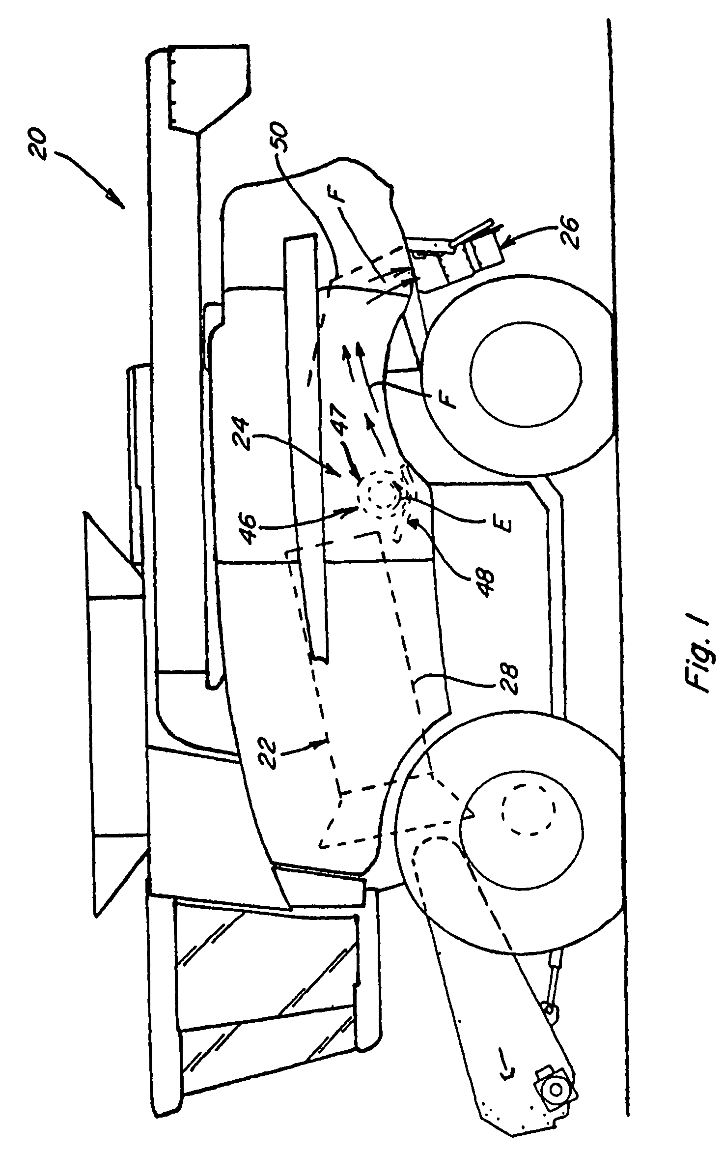
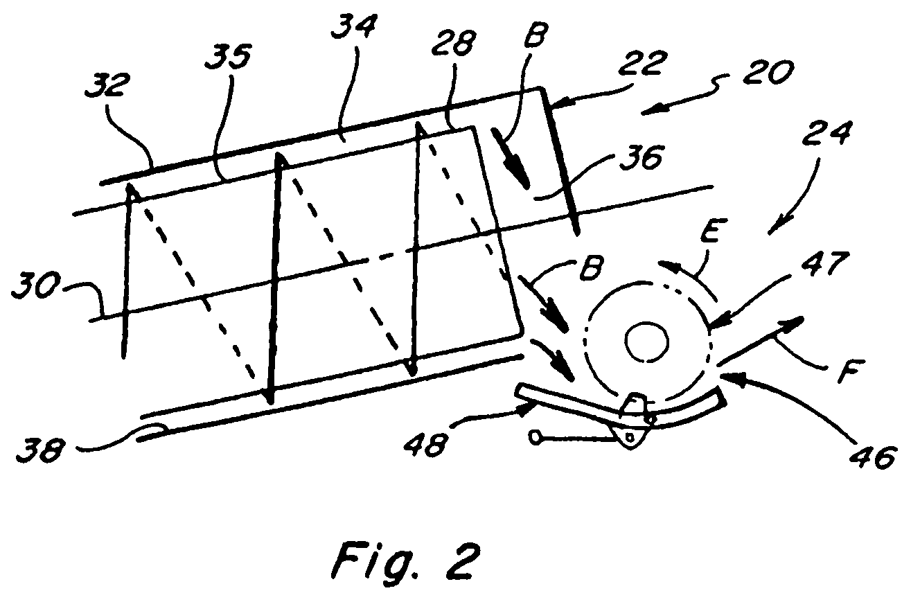
Referring now to the drawings, wherein preferred embodiments of an improved integral chopper assembly that includes the present invention are shown, wherein like numerals refer to like items, wherein certain elements and features may be labeled or marked on a representative basis without each like element or feature necessarily being individually shown, labeled, or marked, and wherein certain elements are labeled and marked in only some, but not all, of the drawing figures, FIGS. 1 and 2 depict a representative agricultural combine 20 that includes a longitudinally axially arranged threshing system 22 and a crop residue treatment and distribution system 24 with a crop residue spreader 26, all of which, except for the improved integral chopper system that is the subject hereof and which is included within the crop residue and distribution system 24, are of well known construction and operation.

As can be generally and essentially observed from a review and study of FIGS. 1-2, threshin...


PUM


Abstract

A rotor tine construction for a rotary element of a crop residue treatment system for effecting improved transport of crop residue along a material flow path and, if a counter knife assembly is spaced from the rotary element across the material flow path, for also effecting improved shear cutting of such crop residue by the knife elements of the counter knife assembly and more efficient operation of the crop residue treatment system, which rotor tine construction includes a base portion generally mountable to the rotary member of the rotary element, at least one rotor tine extending outwardly from such base portion and including three distinct blade edges, one of which forms a trailing edge and the other two of which are upper and lower edge portions forming a leading edge, with the lower and upper edge portions configured and intersecting with one another to form a notch-like indentation along the leading edge at an intersection point P defined to be the point of cut contact position, such that, as the rotary member rotates forwardly the rotor tine is rotated through the material flow path to engage and concentrate engaged lengths of crop residue near intersection point P for an improved cut as such material is moved past the knife elements of the counter knife assembly.

Description

TECHNICAL FIELDThis invention relates generally to crop residue treatment systems and to agricultural equipment and machines that have such systems therewith for effecting the movement of such crop residue and for optionally also rendering crop residue provided thereto into smaller pieces, and especially to crop processors and impact chopper assemblies that have a rotary element or portion, including crop rotor tines arrayed therealong and thereabout, and a counter knife assembly that may be positioned generally parallel to such rotary element such that the rotor tines rotate past the knife elements of the counter knife assembly to interact therewith and to so advance the crop residue passing between the rotary processor element and the counter knife assembly to effect a shearing cut of the crop residue as it passes the counter knife assembly, and even more particularly to an improved rotor tine configuration and arrangement that facilitate improved and more uniform throughput of th...

Claims


Application Information

Patent Timeline
Patent Type & Authority Patents(United States)
IPC IPC(8): A01F12/40
CPCA01D41/1243A01D90/04A01F12/40A01F2015/107
Inventor LAUWERS, ANDREW V.ISAAC, NATHAN E.ROBERGE, MARTIN J.BENES, JASON M.
Owner BLUE LEAF I P INC
Why Eureka
Try Eureka