
Ophthalmological instrument

a technology for ophthalmological instruments and instruments, applied in instruments, medical science, diagnostics, etc., can solve the problems of difficult to achieve the effect of achieving the effect of improving the applicability of ophthalmic instruments, short switching times, and high spectral stability of switch-on emission

Active Publication Date: 2011-01-18
CARL ZEISS MEDITEC AG
View PDF9 Cites 30 Cited by
  • Summary
  • Abstract
  • Description
  • Claims
  • Application Information

AI Technical Summary

Benefits of technology

[0014]It is an object of the present invention to provide a solution for an energetically economic illumination device of improved applicability for an ophthalmic instrument, said device being characterized, in particular, by spectrally selective, very homogeneous generation of light with multiple-channel capability, short switching times and high spectral stability in switch-on emission and short-time emission.
[0015]A particularly advantageous applicative property of this novel illumination device is, for example, the possibility of providing high spectrally selective intensities in the near-UV range of >400 nm, where the ocular media have the greatest scattering power in the visible range, allowing extremely sensitive diagnoses.
[0016]On the other hand, the use of LEDs at 1065 or 1300 nm in the region of the lowest scattering of ocular media and even lower water absorption allows examination, e.g. through cataract lenses, the posterior surface and the posterior capsule membrane thereof.
[0017]Thus, the concept of the invention describes the use of quite specific spectra in combination with very short switch-on and switch-off times, respectively, with high consistency in color, for the purpose of increasing the sensitivity of diagnosis of the eye.

Problems solved by technology

These conventional white light sources, such as e.g. halogen lamps, have the disadvantage that, from an energetic and economic point of view, the light is generated only with a relatively low efficiency of 8-12%.
This disadvantage is even more pronounced where only very narrow spectral ranges, e.g. from the UV range, are used to carry out fluorescence examinations.
Accordingly, this conventional illumination requires very complex technical equipment for the mechanically movable optical filters and for cooling the system.
A further disadvantage of conventional white light sources is their switch-on and switch-off behavior, which is characterized, on the one hand, by relatively long switching times (in the range of >100 ms) and, on the other hand, by variation of the spectral composition of the light during the switch-on phase.
Moreover, halogen lamps have a relatively long warm-up phase.
This is disadvantageous, in particular, in the case of moving objects under examination, such as the eye, because very short exposure times in the ms range are needed here in order to exclude influences of motion when documenting the eye.
However, since there is a clear difference between the optical properties of the light emission of a spiral-wound filament and an LED chip surface, this also has negative effects on the achievable homogeneity.
This means that the light intensity decreases with the cosine to the LED chip surface normal, causing systematic trimming in the slit plane.
Such trimming cannot be avoided completely in case of a “Koehler” illumination, but can only be reduced by limiting the aperture of the condenser lens, which on the other hand strongly reduces the energy efficiency of the source of illumination, however.
All these documents relating to spatially distributed emitters have the disadvantage—in the absence of special devices for homogenization—that the intensity in the field of illumination is not sufficiently homogeneous and does not suffice for a sensitive diagnosis.

Method used


Image

  • Ophthalmological instrument
  • Ophthalmological instrument

Examples


Embodiment Construction

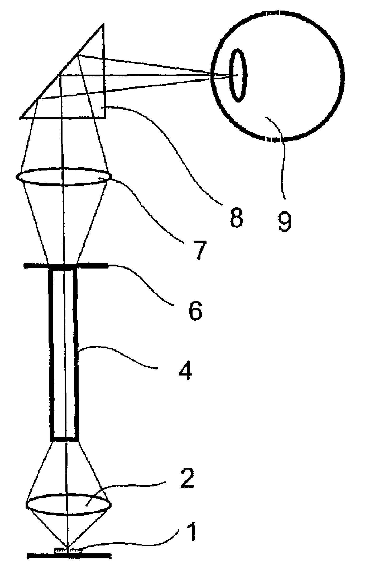
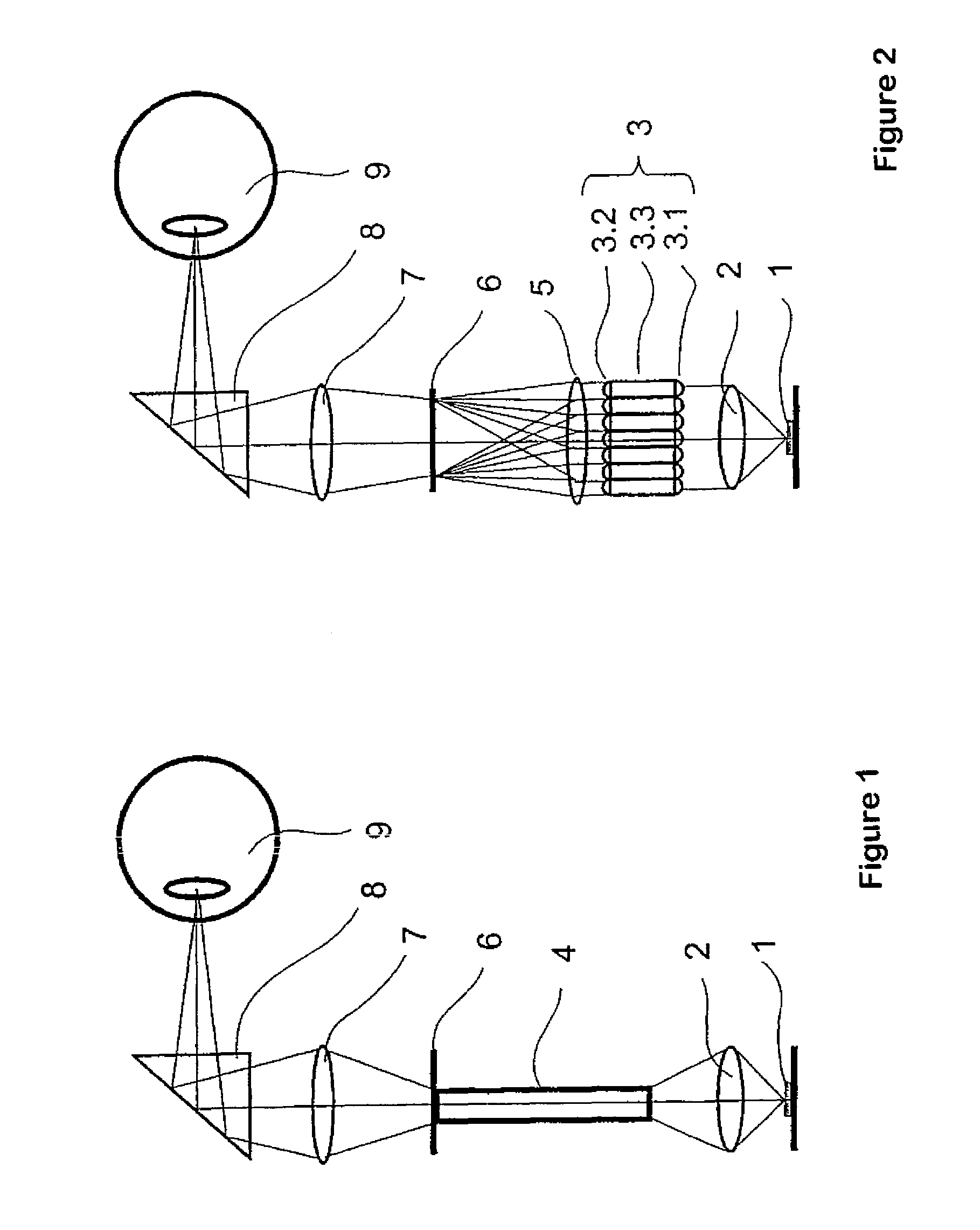
[0021]In the ophthalmic instrument according to the invention—which instrument has homogeneous illumination for observation and / or documentation of an eye and consists of an illumination device including a source of illumination, a homogenizing unit, and a projection device—one or more organic or inorganic sources of radiation with spectrally selective emission are used.

[0022]Controlled by a control unit, these sources of radiation generate continuous and / or pulsed spatial illumination in order to enable, via a digital camera unit, suitably adapted visual and / or digital observation, recording, or output of the examined areas of the eye.

[0023]In this case, in particular, LEDs, SLDs, lasers or O-LEDs are used individually or in combination as organic or inorganic sources of radiation with spectrally selective emission. The source of illumination preferably comprises several sources of radiation emitting in a spectrally selective manner, which have the same and / or different intensity d...


PUM


Abstract

A homogeneously illuminating ophthalmic instrument includes an illumination device having a source of illumination, a homogenizing unit and a projection device, at least one organic or inorganic source of radiation with spectrally selective emission being used as a source of illumination. The illumination generated in this way enables correspondingly adapted visual and / or digital observation, recording or display of the examined regions of the eye by a visualizing unit.

Description

[0001]The present application is a National Phase entry of PCT Application No. PCT / EP2007 / 001527, filed Feb. 22, 2007, which claims priority from German Application Number 10 2006 010 105.7, filed Feb. 28, 2006, the disclosures of which are hereby incorporated by reference herein in their entirety.FIELD OF THE INVENTION[0002]The present invention relates to an instrument for observation, documentation and / or diagnosis of an eye, in particular of the anterior portion of the eye, the iris, the lens, the vitreous body, as well as the fundus of the eye.BACKGROUND OF THE INVENTION[0003]According to the known prior art, classic ophthalmic instruments for examination of the eye use conventional white light sources for illumination, so as to generate an image of the eye's interior that is as natural as possible for the observer. In order to enable examinations in specific spectral ranges, suitable spectral filters are inserted in the beam path following the white light source.[0004]These co...

Claims


Application Information

Patent Timeline
Patent Type & Authority Patents(United States)
IPC IPC(8): A61B3/10A61B3/14
CPCG02B27/0927G02B27/0961G02B27/0994A61B3/14
Inventor LUTHER, EGONKOSCHMIEDER, INGODICK, MANFREDWINTER, JOACHIMMOHRHOLZ, UWEMOHR, THOMASBUBLITZ, DANIELGEISSLER, ENRICO
Owner CARL ZEISS MEDITEC AG
Learn More